Installation and Configuration Manual — EMS TCP 8-Channel Relay Board
1. Introduction
1.1. Legal provisions
The information provided in these documents is property of FENECON GmbH. Publication, in whole or in part, requires the written consent of FENECON GmbH.
Subject to changes and printing errors!
1.2. Qualification of the installer
A qualified installer is a person who has the following experience and training:
-
Setting up, switching on, switching off, disconnecting, earthing, short-circuiting and repairing circuits and devices
-
Standard maintenance and use of protective devices in accordance with current safety standards
-
First aid/emergency care
-
Current knowledge of local regulations, standards and guidelines
Before reading the manual, you should familiarize yourself with the different types of safety warnings. You should also familiarize yourself with the importance of the safety warnings.
| If the devices are not connected in accordance with the standard, this change must be reported to Heckert Solar Service (+49 (0) 9903 6280 0; service@fenecon.de). The configuration can then be modified to meet your requirements. |
| Follow the instructions for the respective device! |
2. Product description
2.1. Scope of delivery
After you receive the shipment, please check to make sure all components are included. Inspect the scope of delivery for damage. If anything is missing or damaged, please contact the supplier immediately. The following components are included in the shipment:
-
Installation and Configuration Manual — EMS TCP 8-Channel Relay Board
-
DIN rail power supply unit (12 V / 1.25 A)
-
Installation instructions — Installation and Configuration Manual — EMS TCP 8-Channel Relay Board
2.2. Prerequisites
For the use of the Installation and Configuration Manual — EMS TCP 8-Channel Relay Board is required:
-
Energiemanagement System (EMS)
EMS is being developed as an open-source project under the name "OpenEMS" in collaboration with many other companies and institutions within the "OpenEMS Association e.V." More information:
EMS App: https://www.fenecon.com/fems-apps/
OpenEMS: https://www.openems.io
EMS is a component of the integrated FENECON energy storage systems and other product combinations consisting of battery inverters and batteries. For more information, visit https://fenecon.com/.
3. Installation and Configuration Manual — EMS TCP 8-Channel Relay Board
3.1. Technical data
Logical control |
Modbus/TCP via network |
Power supply |
9-24 VDC/1 A |
Function |
8 relays, each of which can be used as a normally closed or normally open contact. |
Maximum switching capacities |
|
Assembly |
DIN rail |
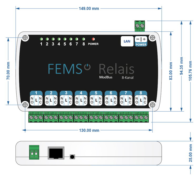
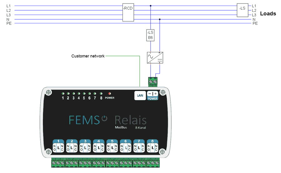
3.2. Standard assignment and connection: Combined heat and power plant (CHP)
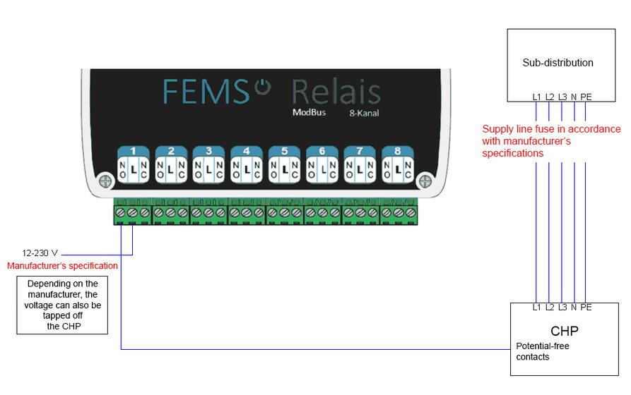
| The CHP unit must be connected to channel 1 by default. |
3.3. Standard configuration and connection: SG-Ready heat pump
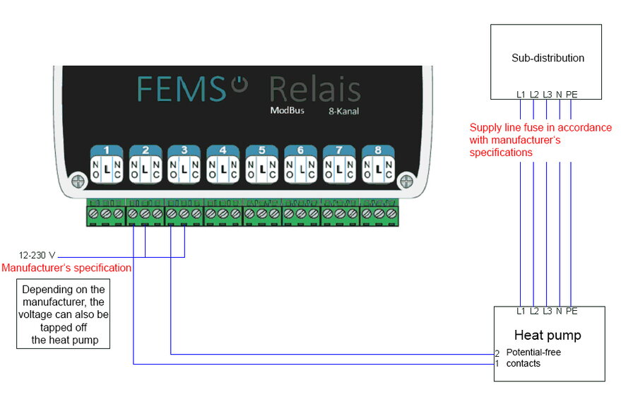
| The heat pump must be connected to channels 2 and 3 as standard. |
3.4. Standard assignment and connection: Heating element 6 kW
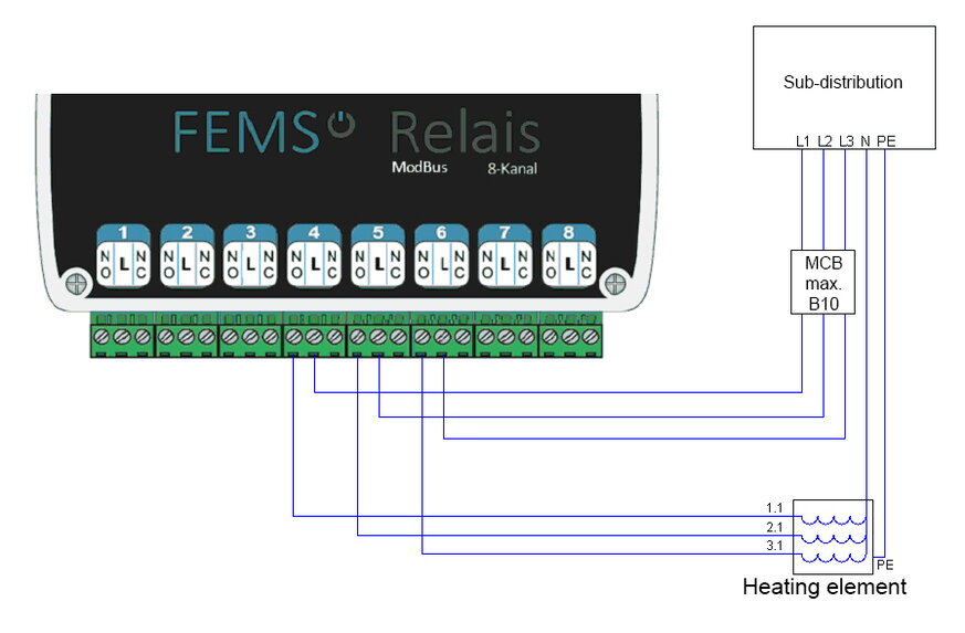
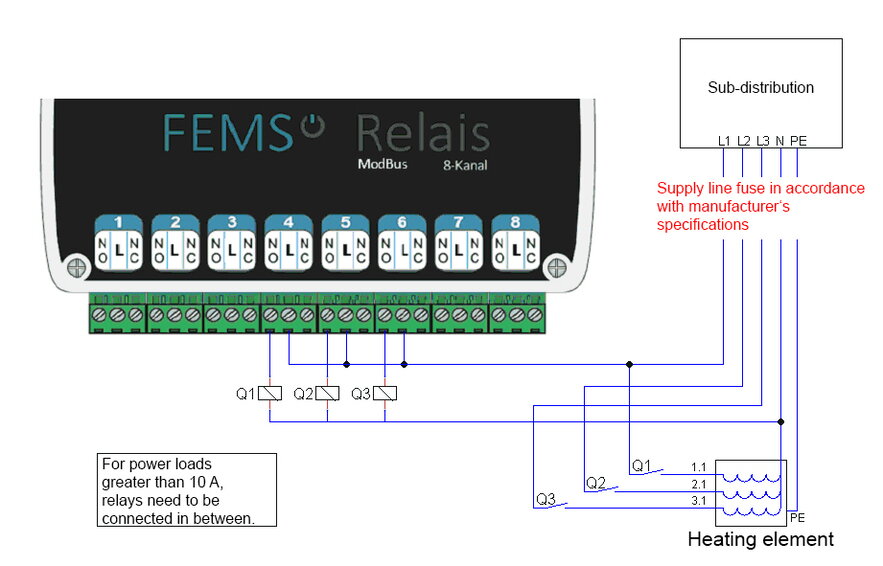
| By default, the heating element should be connected to channels 4, 5, and 6. |
3.5. Standard assignment and connection: Consumer load for Threshold value control
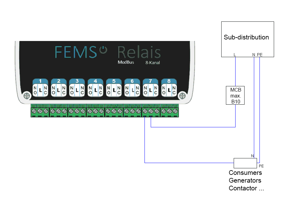
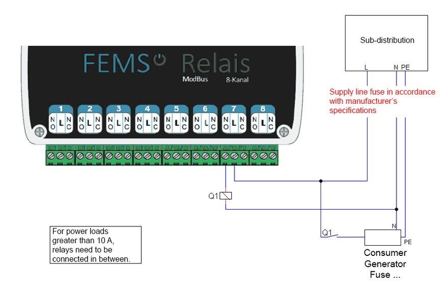
| The sensor for the Threshold Control must be connected to channel 7 by default. |
3.6. Standard assignment and connection: Consumer load for manual relay control
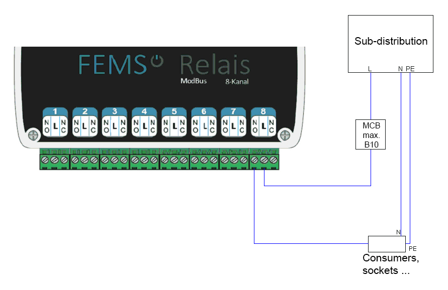
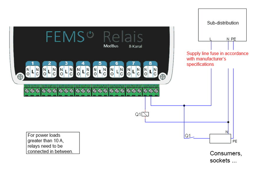
| The consumer load for the manual relay control must be connected to channel 8 by default. |
|
After installing the relay board hardware, you’ll need to install the corresponding app from the EMS App Center. |
3.7. Power over Ethernet (PoE) Operation
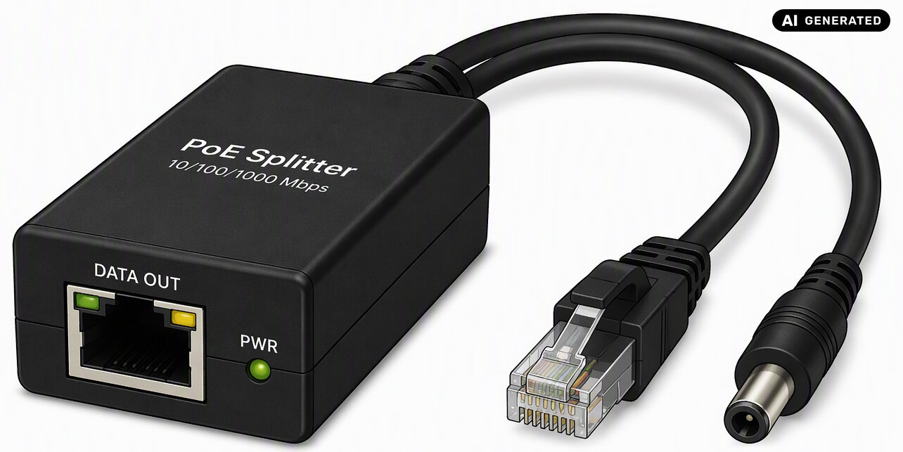
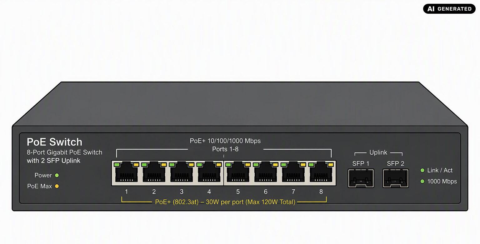
Instead of using the included DIN-rail power supply (12 V/1.25 A), the relay board can also be powered via PoE (Power over Ethernet).
This requires an IEEE-compliant, active PoE splitter or PoE switch that supplies 12 V/1 A or 12 V/2 A. The PoE splitter or switch is connected between the relay board and the network switch.
| PoE splitter | PoE switch |
|---|---|
|
|
| Using a passive PoE splitter or switch may cause damage to the relay board. Please use only an active PoE splitter or switch. |
4. Installing the app
Instructions on how to proceed can be found here.
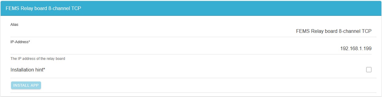
The following window appears during the app installation:
|
To complete the installation of the relay board app, click on Confirm twice.
4.1. Changing the relay board’s static IP address
-
Configure a laptop with the static IP address
192.168.1.1. -
Connect the laptop to the relay board using an Ethernet cable.
-
Use the command
ping 192.168.1.199to check whether the relay board is reachable. -
Open your browser and enter the URL
http://192.168.1.199. -
A window will then appear where you can enter the new network configuration for your own network.