Symphon-E App Modbus/TCP Read Access
1. Symphon-E App Modbus/TCP Read Access
These instructions describe read access to a Heckert Solar electrical energy storage system using the Modbus/TCP API. The basics of the protocol are described first. Then, the functionality of the interface is explained.
|
1.1. Prerequisites
The device accessing the electrical energy storage system (e. g. notebook/PC) must have direct access to the IP address of the EMS - i. e. be connected to the same physical network, for example.
1.2. Basics Modbus/TCP
The Modbus protocol is a communication protocol based on a client/server architecture. It was created in 1979 by Gould-Modicon for communication with its programmable logic controllers. Modbus has become a de facto standard in the industry as it is an open protocol. The Modbus TCP version has been part of the IEC 61158 standard since 2007.
Modbus can be used to connect a client (e. g. a PC/EMS) and several servers (e. g. measurement and control systems, battery storage, PV system, EV charging station). There are two versions: One for the serial interface (EIA-232 and EIA-485) and one for Ethernet. This manual describes the version for Ethernet. TCP/IP packets are used to transmit the data.
Read and write access is possible to the following object types:
Object type |
Access |
Size |
Function code |
Single input/output "Coil" |
read & write |
1-bit |
01 / 05 / 15 |
Single input "Discrete Input" |
read only |
1-bit |
02 |
(Analog) inputs "Input Register" |
read only |
16-bits |
04 |
(Analog) inputs/outputs "Holding Register" |
read & write |
16-bits |
03 / 06 / 16 |
|
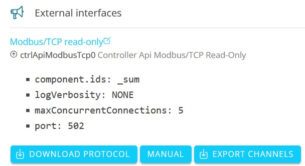
The Modbus interface is configured as follows:
Device address |
IP address of the EMS (e. g. 192.168.0.20) |
Port |
502 |
Unit ID |
1 |
Function Codes |
03 (Read Holding Registers) |
04 (Read Input Registers) |
The interface enables access to the channels of the _sum component by default.
1.3. Modbus table
Via the Online Monitoring you can conveniently download the individual Modbus table for your system as an Excel file as follows:


You can also find the most important data points here in the quick overview:
Address (address) |
Name |
Type |
Value/Description |
Unit |
Access |
200 |
Component-ID |
string16 |
_sum |
RO |
|
222 |
State |
enum16 |
0:Ok, 1:Info, 2:Warning, 3:Fault |
RO |
|
302 |
EssSoc |
uint16 |
State of charge |
Percent [%] |
RO |
303 |
EssActivePower |
float32 |
AC-side active power of the electrical energy storage including excess DC generation with hybrid inverter |
Watt [W] |
RO |
309 |
EssReactivePower |
float32 |
AC-side reactive power of the electrical energy storage |
Volt Ampere Reactive [var] |
RO |
315 |
GridActivePower |
float32 |
Active power at grid connection point |
Watt [W] |
RO |
317 |
GridMinActivePower |
float32 |
Minimum active power measured per grid connection point |
Watt [W] |
RO |
319 |
GridMaxActivePower |
float32 |
Maximum active power per measured active power at the grid connection point |
Watt [W] |
RO |
327 |
ProductionActivePower |
float32 |
Active power of the PV yield and, if applicable, yield from external inverters |
Watt [W] |
RO |
329 |
ProductionMaxActivePower |
float32 |
Maximum measured active power of the PV system |
Watt [W] |
RO |
331 |
ProductionAcActivePower |
float32 |
Active power of the external AC inverters |
Watt [W] |
RO |
339 |
ProductionDcActualPower |
float32 |
Power of the DC generation of the hybrid inverter |
Watt [W] |
RO |
343 |
ConsumptionActivePower |
float32 |
Active power of the electrical consumption |
Watt [W] |
RO |
345 |
ConsumptionMaxActivePower |
float32 |
Maximum active power of electrical consumption ever measured |
Watt [W] |
RO |
351 |
EssActiveChargeEnergy |
float64 |
Cumulative electrical energy of the AC-side battery charging incl. excess PV generation at the hybrid inverter |
Watt hours [Wh] |
RO |
355 |
EssActiveDischargeEnergy |
float64 |
Cumulative electrical energy from electrical energy storage to consumption via AC output of the inverter incl. PV generation |
Watt hours [Wh] |
RO |
359 |
GridBuyActiveEnergy |
float64 |
Cumulative electrical energy from grid consumption |
Watt hours [Wh] |
RO |
363 |
GridSellActiveEnergy |
float64 |
Cumulative electrical energy of the grid feed-in |
Watt hours [Wh] |
RO |
367 |
ProductionActiveEnergy |
float64 |
Cumulative electrical energy of PV generation + external inverter generation |
Watt hours [Wh] |
RO |
371 |
ProductionAcActiveEnergy |
float64 |
Cumulative electrical energy of the external inverters |
Watt hours [Wh] |
RO |
375 |
ProductionDcActiveEnergy |
float64 |
Cumulative electrical energy of the PV generation of the inverter |
Watt hours [Wh] |
RO |
379 |
ConsumptionActiveEnergy |
float64 |
Cumulative electrical consumption |
Watt hours [Wh] |
RO |
383 |
EssDcChargeEnergy |
float64 |
Cumulative DC electrical energy of battery charging |
Watt hours [Wh] |
RO |
387 |
EssDcDischargeEnergy |
float64 |
Cumulative DC electrical energy of storage discharge |
Watt hours [Wh] |
RO |
415 |
EssDischargePower |
float32 |
Actual AC-side active power of the electrical energy storage |
Watt [W] |
RO |
417 |
GridMode |
enum16 |
1:On-Grid, 2:Off-Grid |
RO |
1.4. Example 1: Read access battery charge status with QModMaster
The following is an example of read access to the state of charge (SoC) of the battery using the free tool QModMaster.
Download the tool using this link:
Online: https://sourceforge.net/projects/qmodmaster/
The value of the state of charge is stored as follows (see above):
Address |
Name |
Type |
Value/Description |
Unit |
Access |
302 |
_sum/EssSoc |
uint16 |
Percent [%] |
RO |
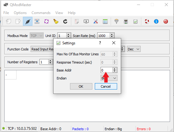
By default, the Base Address is set to 1 in QModbusMaster. This value must be changed to 0. Otherwise, the register addresses from the system profile are shifted by 1.
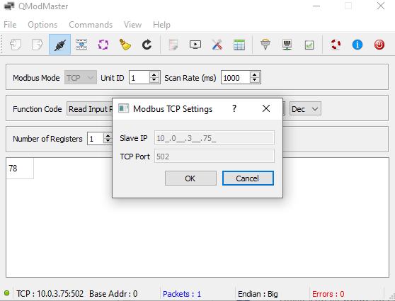
Under Modbus TCP Settings, Slave IP and TCP Port must be configured correctly.
As this is a unit16, a 16-bit word, i. e. a register, must be read out. After setting the values, click on the "Read/Write" menu item. The read value appears below.
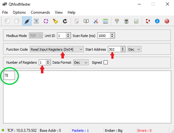
The comparison with Online Monitoring confirms the correctness of the read value.
Other read operations are performed in the same way.