Symphon-E App Modbus/TCP Write Access
1. Introduction
Dear customer,
Thank you for choosing the "Symphon-E App Modbus/TCP Write Access". You are welcome to send us your suggestions so that we can further improve the quality of our products.
2. Installing the app
When you ordered the "Symphon-E App Modbus/TCP Write Access", you received a 16-digit license key. You can use this license key to redeem the app independently in the EMS App Center.
Instructions on how to proceed can be found here.
3. Symphon-E App Modbus/TCP Write Access
These instructions describe write access to a Heckert Solar electrical energy storage system using the Modbus/TCP API. The basics of the protocol are described first. The functionality of the interface is then explained.
|
3.1. Prerequisites
The device accessing the electrical energy storage system (e. g. notebook/PC) must have direct access to the IP address of the EMS - i. e. be connected to the same physical network, for example.
3.2. Basics Modbus/TCP
The Modbus protocol is a communication protocol based on a client/server architecture. It was created in 1979 by Gould-Modicon for communication with its programmable logic controllers. Modbus has become a de facto standard in the industry as it is an open protocol. The Modbus TCP version has been part of the IEC 61158 standard since 2007.
Modbus can be used to connect a client (e. g. a PC/EMS) and several servers (e. g. measurement and control systems, battery storage, PV system, EV charging station). There are two versions: One for the serial interface (EIA-232 and EIA-485) and one for Ethernet. This manual describes the version for Ethernet. TCP/IP packets are used to transmit the data.
Read and write access is possible to the following object types:
Object type |
Access |
Size |
Function code |
Single input/output "Coil" |
read & write |
1-bit |
01 / 05 / 15 |
Single input "Discrete Input" |
read only |
1-bit |
02 |
(Analog) inputs "Input Register" |
read only |
16-bits |
04 |
(Analog) inputs/outputs "Holding Register" |
read & write |
16-bits |
03 / 06 / 16 |
The Modbus interface is configured as follows:
Device address |
IP address of the EMS (e. g. 192.168.0.20) |
Port |
*502 |
Unit ID |
*1 |
Function codes |
03 (Read Holding Registers) |
04 (Read Input Registers) |
|
06 (Write Single Holding Register) |
|
16 (Write Multiple Holding Registers) |
The interface enables access to the channels of the _sum and ess0 components by default.
3.3. Modbus table
Via the Online Monitoring you can conveniently download the individual Modbus table for your system as an Excel file as follows:
In the [fig3:modbus_detail view] you can start the download via the "DOWNLOAD PROTOCOL" button.
You can also find the most important data points here in the quick overview:
Address (address) |
Name |
Type |
Value/Description |
Unit |
Access |
200 |
Component-ID |
string16 |
_sum |
RO |
|
222 |
State |
enum16 |
0:Ok, 1:Info, 2:Warning, 3:Fault |
RO |
|
302 |
EssSoc |
uint16 |
State of charge |
Percent [%] |
RO |
303 |
EssActivePower |
float32 |
AC-side active power of the electrical energy storage including excess DC generation with hybrid inverter |
Watt [W] |
RO |
309 |
EssReactivePower |
float32 |
AC-side reactive power of the electrical energy storage |
Volt Ampere Reactive [var] |
RO |
315 |
GridActivePower |
float32 |
Active power at grid connection point |
Watt [W] |
RO |
317 |
GridMinActivePower |
float32 |
Minimum active power measured per grid connection point |
Watt [W] |
RO |
319 |
GridMaxActivePower |
float32 |
Maximum active power per measured active power at the grid connection point |
Watt [W] |
RO |
327 |
ProductionActivePower |
float32 |
Active power of the PV yield and, if applicable, yield from external inverters |
Watt [W] |
RO |
329 |
ProductionMaxActivePower |
float32 |
Maximum measured active power of the PV system |
Watt [W] |
RO |
331 |
ProductionAcActivePower |
float32 |
Active power of the external AC inverters |
Watt [W] |
RO |
339 |
ProductionDcActualPower |
float32 |
Power of the DC generation of the hybrid inverter |
Watt [W] |
RO |
343 |
ConsumptionActivePower |
float32 |
Active power of the electrical consumption |
Watt [W] |
RO |
345 |
ConsumptionMaxActivePower |
float32 |
Maximum active power of electrical consumption ever measured |
Watt [W] |
RO |
351 |
EssActiveChargeEnergy |
float64 |
Cumulative electrical energy of the AC-side battery charging incl. excess PV generation at the hybrid inverter |
Watt hours [Wh] |
RO |
355 |
EssActiveDischargeEnergy |
float64 |
Cumulative electrical energy from electrical energy storage to consumption via AC output of the inverter incl. PV generation |
Watt hours [Wh] |
RO |
359 |
GridBuyActiveEnergy |
float64 |
Cumulative electrical energy from grid consumption |
Watt hours [Wh] |
RO |
363 |
GridSellActiveEnergy |
float64 |
Cumulative electrical energy of the grid feed-in |
Watt hours [Wh] |
RO |
367 |
ProductionActiveEnergy |
float64 |
Cumulative electrical energy of PV generation + external inverter generation |
Watt hours [Wh] |
RO |
371 |
ProductionAcActiveEnergy |
float64 |
Cumulative electrical energy of the external inverters |
Watt hours [Wh] |
RO |
375 |
ProductionDcActiveEnergy |
float64 |
Cumulative electrical energy of the PV generation of the inverter |
Watt hours [Wh] |
RO |
379 |
ConsumptionActiveEnergy |
float64 |
Cumulative electrical consumption |
Watt hours [Wh] |
RO |
383 |
EssDcChargeEnergy |
float64 |
Cumulative DC electrical energy of battery charging |
Watt hours [Wh] |
RO |
387 |
EssDcDischargeEnergy |
float64 |
Cumulative DC electrical energy of storage discharge |
Watt hours [Wh] |
RO |
415 |
EssDischargePower |
float32 |
Actual AC-side active power of the electrical energy storage |
Watt [W] |
RO |
417 |
GridMode |
enum16 |
1:On-Grid, 2:Off-Grid |
RO |
Address (address) |
Name |
Type |
Value/Description |
Unit |
Access |
500 |
Component-ID |
string16 |
ess0 |
RO |
|
522 |
State |
enum16 |
0:Ok, 1:Info, 2:Warning, 3:Fault |
RO |
|
602 |
SoC |
uint16 |
State of charge |
Percent [%] |
RO |
603 |
GridMode |
enum16 |
1:On-Grid, 2:Off-Grid |
RO |
|
604 |
ActivePower |
float32 |
Calculated charging or discharging power1 |
Watt [W] |
RO |
608 |
MinCellVoltage |
float32 |
Minimum cell voltage |
millivolts [mV] |
RO |
610 |
MaxCellVoltage |
float32 |
Maximum cell voltage |
millivolt [mV] |
RO |
612 |
MinCellTemperature |
float32 |
Maximum cell temperature |
degrees Celsius [C] |
RO |
614 |
MaxCellTemperature |
float32 |
Maximum cell temperature |
degrees Celsius [C] |
RO |
616 |
ess0/Capacity |
float32 |
Installed storage capacity |
WattHours [Wh] |
RO |
618 |
ess0/MaxApparentPower |
float32 |
Apparent power of the system |
VoltAmperes [VA] |
RO |
702 |
Minimum Power Set-Point |
float32 |
Minimum power set-point — Lower limit for the storage power at this time. If a lower value is written to 706, this value is converted 1.2 |
Watt [W] |
RO |
704 |
Maximum Power Set-Point |
float32 |
Maximum Power Set-Point — Upper limit for the memory power at this time. If a higher value is written to 706, this value is converted 1.2 |
Watt [W] |
RO |
706 |
SetActivePowerEquals |
float32 |
Default charging or discharging power1 |
Watt [W] |
WO |
708 |
SetReactivePowerEquals |
float32 |
Default reactive power |
Volt Ampere Reactive [var] |
WO |
710 |
SetActivePowerLessOrEquals |
float32 |
Set maximum discharge power |
Watt [W] |
WO |
712 |
SetReactivePowerLessOrEquals |
float32 |
Set maximum reactive power |
Volt Ampere Reactive [var] |
WO |
714 |
SetActivePowerGreaterOrEquals |
float32 |
Set maximum charging power |
Watt [W] |
WO |
716 |
SetReactivePowerGreaterOrEquals |
float32 |
Set minimum reactive power |
Volt Ampere Reactive [var] |
WO |
1 Negative values correspond to battery charging — Positive values correspond to battery discharging.
2 Factors such as D-rating and mains voltage reduce the maximum possible power, but are not yet considered in this calculation.
| The registers for reactive power specifications cannot currently be used for home systems. |
3.4. Visualization and configuration
After installing the "Symphon-E App Modbus/TCP Write Access", you will see the following widget in your live monitoring:

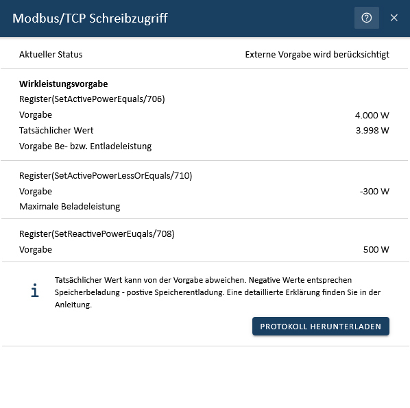
The flat widget shows the current status of the external write specifications. As soon as a register is overwritten, the status changes from "No external specification available" to "External specification is taken into account".
Click on the widget to open the detailed view:
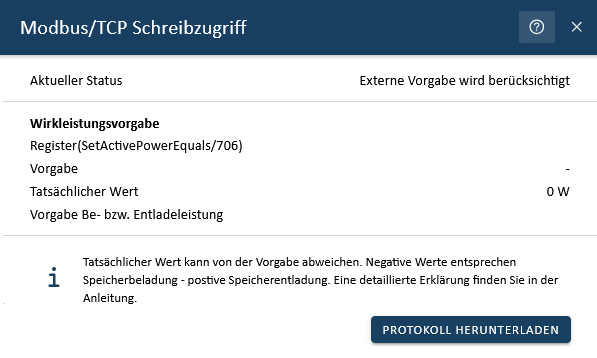
In the detailed view, you will find an overview of the respective registers. This overview contains your set default value for the active power default register (SetActivePowerEquals/706) as well as the actual value that can be technically implemented. Only the default value is displayed for all other registers. As soon as other registers are overwritten, the detailed view is automatically updated.
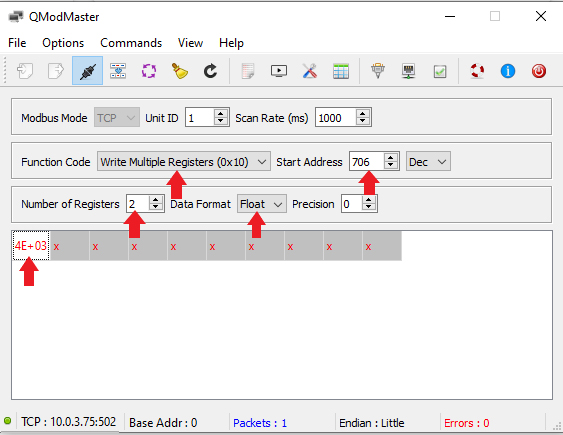
3.5. Example 1: Write access to EssActivePower with QModMaster
In the following, the write access for setting the EssActivePower using the free tool QModMaster is shown as an example. This allows the function of the Controller Fix Active Power Symmetric to be simulated.
The value is stored as follows (see above):
Address |
Name |
Type |
Value/Description |
Unit |
Access |
706 |
ess0/SetActivePowerEquals |
float32 |
Watt [W] |
WO |
|
As this is a float32, two 16-bit words, i. e. two registers, must be written. In this example, the electrical energy storage is to be unloaded with 4000 (4E+03) watts. The value can be entered directly as a decimal number in the register, whereby the data format Float must be selected. After setting the value, click on the "Read/Write" menu item to perform the write operation.
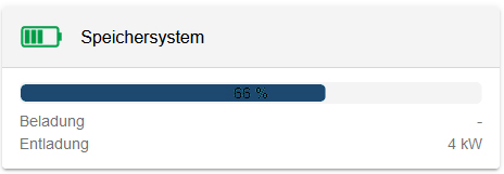
The comparison with Online Monitoring confirms the correctness of the written value:
|
Other write operations are carried out in the same way.
3.6. Watchdog
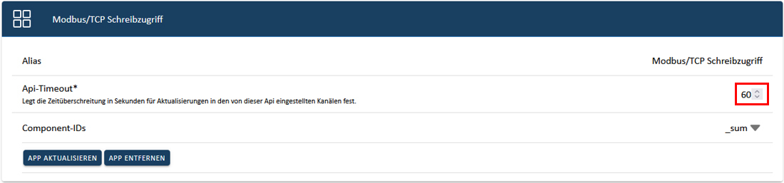
The "Symphon-E App Modbus/TCP Write Access" has an integrated "watchdog" functionality. This ensures that a loading or unloading specification is terminated if the connection is lost (e. g. failure of the higher-level controller or the network). In the standard configuration, this "API timeout" is set to 60 seconds. A write specification is therefore implemented for 60 seconds. In order to implement continuous control, we recommend a new specification after half of the configured time, i. e. in this case after 30 seconds. If no new write specification is made within 60 seconds, charging or discharging is terminated.
The "API timeout" can be changed via the app configuration in the App Center. A value of "0 seconds" deactivates the watchdog function.

3.7. Reading back the values written to EMS
If values are specified to the electrical energy storage system via write access (e.g. to 706_SetActivePowerEquals), this reflects back its actual converted values (e.g. to 604_ActivePower).
This section describes how to read back the values written to write registers 702 to 716 before they were converted by EMS.
Example
An electrical energy storage system with 92 kW output, write specification to 706 = 100 kW:
→ Result on 604_ActivePower = 92 kW (maximum power of the system).
→ Result on xxx_ActualSetActivePowerEquals = 100 kW.
The following table shows the reading registers for the corresponding writing registers:
| Write-only register | Read-only register | ||
|---|---|---|---|
Address |
Name |
Address |
Name |
702 |
Minimum Power Set-Point |
xxx |
ctrlApiModbusTcp0/Ess0ActivePowerLimit |
704 |
Maximum Power Set-Point |
xxx |
ctrlApiModbusTcp0/Ess0ReactivePowerLimit |
706 |
ess0/SetActivePowerEquals |
xxx |
ctrlApiModbusTcp0/ActualSetActivePowerEquals |
708 |
ess0/SetReactivePowerEquals |
xxx |
ctrlApiModbusTcp0/ActualSetReactivePowerEquals |
710 |
ess0/SetActivePowerLessOrEquals |
xxx |
ctrlApiModbusTcp0/ActualSetActivePowerLessOrEquals |
712 |
ess0/SetReactivePowerLessOrEquals |
xxx |
ctrlApiModbusTcp0/ActualSetReactivePowerLessOrEquals |
714 |
ess0/SetActivePowerGreaterOrEquals |
xxx |
ctrlApiModbusTcp0/ActualSetActivePowerGreaterOrEquals |
716 |
ess0/SetReactivePowerGreaterOrEquals |
xxx |
ctrlApiModbusTcp0/ActualSetReactivePowerGreaterOrEquals |
| "xxx" is the system-dependent register number and must always be checked! |
3.7.1. Installation
First install the Symphon-E App write access as usual via the App Center.
After successfully installing the Symphon-E App write access, configure the app (see edit Symphon-E App):
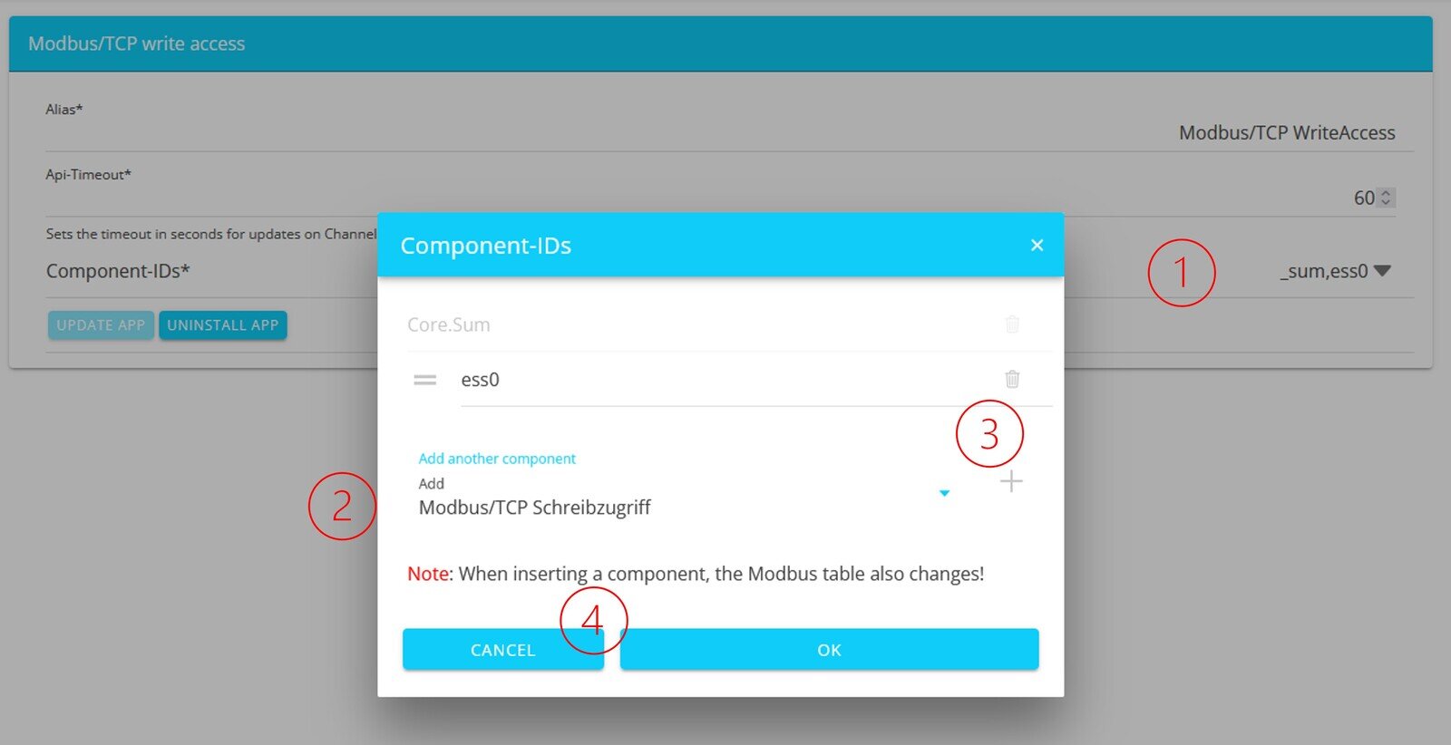
Under "Component IDs (1)", select "Modbus/TCP Write Access" (2) and add with the plus (3). Then accept (4) and update the app.
Then download the Modbus register again. There you will find the registers marked with "xxx" above.