Symphon-E 6, 10 & 15 assembly and operating instructions
1. About these instructions
Personnel must have carefully read and understood these installation and service instructions before starting any work.
1.1. Version/revision
Version/ Revision |
Änderung |
Datum |
Name |
2024.06.1 |
Entwurf Erstellung |
10.06.2024 |
FENECON GW |
2024.11.1 |
Fertigstellung |
14.11.2024 |
FENECON MR |
2024.11.2 |
Update - Illustrationen |
20.11.2024 |
FENECON MR |
2024.11.3 |
Update - Lieferumfang |
29.11.2024 |
FENECON MR |
2025.1.1 |
Integration Feuerwehrhinweis |
27.01.2025 |
FENECON PM |
1.2. Darstellungskonventionen
|
||
|
||
|
||
|
1.3. Structure of warning notices
If observed, warnings protect against possible personal injury and damage to property and use the signal word to classify the magnitude of the danger.
|
Source of the danger |
Danger sign
The danger sign indicates warnings that warn of personal injury test.
Source of danger
The source of danger indicates the cause of the hazard.
Possible consequences of non-compliance
The possible consequences of ignoring the warning are, for example, crushing, burns or other serious injuries.
Measures/Prohibitions
Measures/prohibitions include actions that must be taken to avoid a hazard (e.g. stopping the drive) or that are prohibited to avoid a hazard.
1.4. Terms and abbreviations
The following terms and abbreviations are used in the installation and service instructions:
| Term/Abbreviation | Meaning |
|---|---|
AC |
Alternating Current |
CHP |
Combined heat and power plant |
BMS |
Battery Management System |
DC |
Direct Current |
EMS |
Energy Management System |
Energy meter |
Electricity meter for the inverter at the grid connection point |
EMS |
Energiemanagement System |
IBN |
Commissioning |
MPPT |
Maximum Power Point Tracking Finder for the maximum power point |
GCP |
grid connection point |
PE |
Protective conductor |
PV |
Photovoltaic |
RTE |
Round-Trip-Efficiency (RTE) |
SG-Ready |
Smart-Grid-Ready — Preparation of the heat pump for external control |
SoC |
State of Charge |
SoH |
State of Health — State of ageing |
VDE |
German Association for Electrical, Electronic & Information Technologies e. V. |
Widget |
Component of Online Monitoring |
1.5. Scope of delivery
| Item | Component | Amount | Comment |
|---|---|---|---|
1 |
Symphon-E 6, 10 & 15 inverter |
1 |
model is system-dependent (6, 10 or 15 kW) |
2 |
Symphon-E 6, 10 & 15 EMS box |
1 |
Energiemanagement System incl. |
3 |
Symphon-E 6, 10 & 15 Parallel switch box |
1 |
optional for second Symphon-E 6, 10 & 15 battery tower |
4 |
Symphon-E 6, 10 & 15 Extension box |
1 |
optional for third and fourth Symphon-E 6, 10 & 15 battery tower |
5 |
Symphon-E 6, 10 & 15 BMS box |
1 |
per Symphon-E 6, 10 & 15 battery tower |
6 |
Symphon-E 6, 10 & 15 Battery module |
depending on the capacity ordered |
|
7 |
Symphon-E 6, 10 & 15 Base |
1 |
per Symphon-E 6, 10 & 15 battery tower |
2. Security
2.1. Systembeschreibung
The electrical energy storage system is used for electrical energy storage in rechargeable lithium iron phosphate battery modules (charging) and the provision of electrical energy (discharging). This charging and discharging process takes place via a connected Symphon-E 6, 10 & 15 inverter. All processes of the electricity storage system are monitored and controlled by the EMS. The system may only be used in compliance with the permitted technical data (see chapter Technical data).
2.2. Qualification of the staff
The system may only be installed and maintained by qualified personnel.
Qualified personnel must be deployed for the intended use, installation and maintenance of the system. The area of responsibility, competence and supervision of the personnel must be precisely regulated by the operator.
2.2.1. Elektro-Fachpersonal
Zu Elektro-Fachpersonal zählen Personen, die
-
are able to carry out work on electrical systems due to their technical training, knowledge and experience as well as knowledge of the relevant standards and regulations.
-
have been commissioned and trained by the operator to carry out work on electrical systems and equipment of the battery system.
-
are familiar with how the battery system works.
-
recognize hazards and prevent them by taking appropriate protective measures.
2.3. Intended use
The {ems-name-4} is a modular electrical energy storage system. In particular, this includes a BMS (battery management system), the Energiemanagement System (EMS), battery modules and bases. All processes of the electrical energy storage system are monitored and controlled by EMS.
Any other use is not an intended use.
2.4. Reasonably foreseeable misuse
All applications that do not comply with the intended use are considered misuse.
Work on live parts is generally not permissible. Electrical work must only be carried out by qualified electricians.
The following safety rules must be observed for all work on electrical components:
-
Freischalten
-
Secure against restarting
-
Determine absence of voltage
-
Earthing and short-circuiting
-
Cover or shield neighboring live parts
|
Non-compliance with the safety rules is considered a reasonably foreseeable misuse. |
Other misuses include in particular:
-
improper transportation, installation or assembly at a location, trial operation or operation that could damage the Symphon-E 6, 10 & 15.
-
Change in the specified technical characteristics, including the individual components.
-
Change or deviation of the specified connected loads.
-
functional or structural changes.
-
Operating the product in a faulty or defective condition.
-
improper repairs.
-
operation without protective devices or with defective protective devices.
-
Disregarding the information in the original installation and service instructions.
-
Unauthorized or unauthorized access via the control unit or the network.
-
das Einspielen von Firmware-Updates, die nicht über Heckert Solar bezogen wurden.
-
Fire, open light and smoking in the vicinity of the storage system.
-
Inadequate ventilation at the installation site.
-
unauthorized changes and actions to the electrical energy storage system.
-
Use as mobile energy storage.
-
Direct use in a PV system (integration via an AC-coupled grid is possible).
2.5. Area of application — Electromagnetic compatibility (EMC)
The low-voltage equipment is intended for use in the following areas of application:
-
General information (public)
Use in other areas of application is not in accordance with the intended use.
2.6. General information on the Symphon-E 6, 10 & 15 electrical energy storage system
The product must be positioned in such a way that sufficient room for movement can be guaranteed for service and maintenance personnel in every phase of the product’s life. The product life depends on the operating life and maintenance intervals carried out by qualified personnel. The operating life is particularly influenced by preventive maintenance and servicing. The operating life is limited to 15 years by the manufacturer.
-
Only qualified electricians are authorized to install battery modules and make cable connections.
-
The power storage system must only be used under the specified charging/discharging conditions (see chapter Technical data).
-
Do not immerse the power storage system in water, moisten it or touch it with wet hands.
-
Keep the system and its components away from water sources
-
Keep the power storage system away from children and animals
-
The electrical energy storage system can cause electric shock and burns due to short-circuit currents.
-
Do not expose the electrical energy storage system to heat
-
Do not attempt to crush or open battery modules
-
Do not use battery modules that have fallen down.
-
Set up/store the electrical energy storage system in a cool place
-
Das Stromspeichersystem nicht mehr verwenden, wenn während der Montage, des Ladens, des normalen Betriebs und/oder der Lagerung Farbveränderungen oder mechanische Schäden festgestellt werden.
-
Eye and skin contact with leaked electrolyte solution has to be avoided. After contact with eyes or skin, rinse/clean immediately with water and seek medical advice. Delayed treatment can cause serious health damage.
-
Do not expose the electrical energy storage system to open fire.
-
Do not set up or use the electrical energy storage system near open fires, heaters or high-temperature sources.
-
The heat can cause insulation to melt and the safety ventilation to be damaged. This can lead to overheating, explosion or fire in the battery modules.
-
If the protective devices are damaged, abnormal charging currents and voltages can cause a chemical reaction in the battery modules, leading to overheating, explosion and even fire in the battery modules.
-
Do not connect the plug contacts of the BMS box in reverse.
-
Do not short-circuit battery modules.
-
Do not touch the battery module connectors (+) and (-) directly with a wire or metal object (e.g. metal chain, hairpin). In the event of a short circuit, excessive current can be generated, which can lead to overheating, explosion or fire of the battery modules.
-
Do not throw or drop parts of the power storage system.
-
Do not apply any mechanical force to the electrical energy storage system. The battery modules can be damaged and short circuits can occur, which can lead to overheating, explosion or fire of the battery modules.
-
No soldering work may be carried out on the power storage system. Heat introduced during soldering can damage the insulator and the safety ventilation mechanism and lead to overheating, explosion or fire of the battery modules.
-
The battery modules must not be dismantled or modified. The battery modules contain a safety mechanism and a protective device, damage to which can lead to overheating, explosion or fire of the battery modules.
-
Only use the battery modules as intended. Improper use can lead to overheating, explosion or fire of the battery modules.
-
Read the instructions for installation and operation to avoid damage due to incorrect operation.
-
The battery modules may have insufficient cell voltage after a long storage period. If this is the case, please contact the service department
-
Do not expose the battery modules to high voltages.
-
Place the battery modules on level surfaces.
-
Do not place any objects on the Symphon-E 6, 10 & 15 battery tower.
-
Do not step on the power storage system.
2.6.1. Installation, operation and maintenance
|
When carrying out maintenance, servicing and cleaning work, ensure that the product is switched off in a safe manner and secured against being switched on again. In addition, all instructions in this manual must be followed. |
Always observe the following safety instructions when installing, operating or maintaining the battery modules:
-
The assembly of the Symphon-E 6, 10 & 15, the installation of the battery modules and the establishment of the cable connections as well as the expansion of the system may only be carried out by qualified electricians.
-
During maintenance work, stand on dry insulating objects and do not wear any metal objects/jewelry (e.g. watches, rings and necklaces) during maintenance work/operation.
-
Use insulated tools and wear personal protective equipment.
-
Do not touch two charged contacts with a potential difference.
-
Measure the battery voltage with a multimeter and ensure that the output voltage is 0 V in OFF mode.
-
If an anomaly is detected, switch off the battery tower(s) immediately.
-
Only continue the maintenance work after the causes of the anomaly have been eliminated.
-
The battery modules can cause an electric shock and burns due to high short-circuit currents.
-
Install battery modules in locations with good natural ventilation.
2.6.2. Fire protection
-
Do not expose the power storage system to direct sunlight.
-
Avoid contact with conductive objects (e. g. wires).
-
Keep heat and fire sources, flammable, explosive and chemical materials away from the power storage system.
-
Do not dispose of the Symphon-E 6, 10 & 15 battery modules in a fire due to the risk of explosion.
2.6.3. Storage
-
Area: Fireproof indoors/outdoors; with suitable weather protection
-
Air temperature: -20 °C to 40 °C
-
Relative humidity: max. 50 % at +40 °C.
-
Do not store battery modules (lithium iron phosphate batteries) with flammable or toxic objects
-
Store battery modules with safety defects separately from undamaged battery modules.
|
Lagerung länger als 12 Monate
|
2.7. Operating resources
2.7.1. Electrolyte solution of the battery modules
-
Electrolyte solution is used in the battery modules (lithium iron phosphate).
-
The electrolyte solution in the battery modules is a clear liquid and has a characteristic odor of organic solvents.
-
The electrolyte solution is flammable.
-
The electrolyte solution in the battery modules is corrosive.
-
Do not inhale the vapors.
-
If the electrolyte solution is swallowed, induce vomiting.
-
Leave the contaminated area immediately after inhaling the vapors.
-
Eye and skin contact with leaked electrolyte solution must be avoided.
-
Contact with electrolyte solution can cause severe burns to the skin and damage to the eyes.
-
After skin contact: Immediately wash skin thoroughly with neutralizing soap and consult a doctor if skin irritation persists.
-
After eye contact: Immediately flush eye(s) with running water for 15 minutes and seek medical advice.
-
|
Delayed treatment can cause serious damage to health. |
2.8. Residual risk
|
Warning of electrical voltage Work on electrical equipment must only be carried out by qualified electricians from the manufacturer or by specifically-authorized, trained electricians and in compliance with the safety regulations. |
|
Unknown error messages Unknown errors and attempts to rectify them can damage the product. |
|
All doors, emergency exits and areas around the electrical energy storage system must remain clear; do not obstruct escape routes! |
|
The user is responsible for the ground conditions outside the system. However, the battery system’s housing is sealed so that no electrolyte can escape. |
2.9. Behavior in emergency situations
Proceed as follows in emergency situations:
-
Das Stromspeichersystem vom Netz trennen
-
Remove from the danger zone
-
Secure the danger zone
-
The responsible persons inform
-
Alert a doctor if necessary
2.10. Pictograms
Pictograms on the system indicate dangers, prohibitions and instructions. Illegible or missing pictograms must be replaced by new ones.
| Piktogramm | Bedeutung | Beschreibung |
|---|---|---|

|
Warnung vor gefährlicher elektrischer Spannung |
Piktogramm am Gehäuse, und Kennzeichnung von Komponenten, bei denen nicht klar zu erkennen ist, dass sie elektrische Betriebsmittel enthalten, die Anlass für ein Risiko durch elektrischen Schlag sein können. |

|
Allgemeines Warnzeichen |
|

|
Warnung vor Gefahren durch das Aufladen von Batterien |
Piktogramm am Gehäuse und Kennzeichnung von Komponenten, bei denen nicht klar zu erkennen ist, dass sie elektrische Betriebsmittel enthalten, die Anlass für ein Risiko durch das Aufladen von Batterien sein können. |

|
Keine offene Flamme; Feuer, offene Zündquelle und Rauchen verboten |
Piktogramm am Gehäuse und Kennzeichnung von Komponenten, bei denen nicht klar zu erkennen ist, dass sie elektrische Betriebsmittel enthalten, die Anlass für ein Risiko durch offene Flammen, Feuer, offene Zündquellen und Rauchen sein können. |

|
Schutzerdungskennzeichen |
|

|
Getrennte Sammlung von Elektro- und Elektronikgeräten |
|

|
Anleitung beachten |
|

|
Kopfschutz benutzen |
|

|
Fußschutz benutzen |
|

|
Handschutz benutzen |
|
CE-Kennzeichen |
||

|
Produkt ist recyclingfähig. |
2.11. Operating materials/equipment
2.11.1. Electrolyte solution of the battery modules
-
Electrolyte solution is used in the battery modules (lithium iron phosphate).
-
The electrolyte solution in the battery modules is a clear liquid and has a characteristic odor of organic solvents.
-
The electrolyte solution is flammable.
-
The electrolyte solution in the battery modules is corrosive.
-
Contact with electrolyte solution can cause severe burns to the skin and damage to the eyes.
-
Do not inhale the vapors.
-
If the electrolyte solution is swallowed, induce vomiting.
-
Leave the contaminated area immediately after inhaling the vapors.
-
Eye and skin contact with leaked electrolyte solution must be avoided.
-
After skin contact: Immediately wash skin thoroughly with neutralizing soap and consult a doctor if skin irritation persists.
-
After eye contact: Immediately flush eye(s) with running water for 15 minutes and seek medical advice.
-
Delayed treatment can cause serious damage to health.
2.11.2. Electrical equipment
-
Work on electrical equipment may only be carried out by qualified electricians.
-
Bei allen Arbeiten an elektrischen Komponenten sind die fünf Sicherheitsregeln einzuhalten:
-
Disconnect.
-
Secure against restarting.
-
Spannungsfreiheit feststellen.
-
Earthing and short-circuiting.
-
Cover or shield neighboring live parts.
-
-
Maintenance work may only be carried out by trained specialist personnel (service personnel).
-
Vor Beginn von Arbeiten Sichtkontrollen auf Isolier- und Gehäuseschäden durchführen.
-
The system must never be operated with faulty or non-operational electrical connections.
-
To avoid damage, lay supply lines without crushing and shearing points.
-
Zur Instandhaltung dürfen an unisolierten Leitern und Anschlussklemmen nur isolierte Werkzeuge verwendet werden.
-
Switch cabinets (e. g. inverter housing) must always be kept locked. Only authorized personnel with appropriate training and safety instructions (e. g. service personnel) should be allowed access.
-
The inspection and maintenance intervals for electrical components specified by the manufacturer must be observed.
-
Um Beschädigungen zu vermeiden, Versorgungsleitungen ohne Quetsch- und Scherstellen verlegen
-
If the power supply is disconnected, specially marked external circuits may still be live!
-
Manche Betriebsmittel (z. B. Wechselrichter) mit elektrischem Zwischenkreis können nach Freischaltung für eine gewisse Zeit noch gefährliche Restspannungen bevorraten. Vor Arbeitsbeginn an diesen Anlagen ist die Spannungsfreiheit zu prüfen.
2.12. Personal protective equipment
Depending on the work on the system, personal protective equipment must be worn:
-
Sicherheitsschuhe
-
Protective gloves, cut-resistant if necessary
-
Schutzbrille
-
Schutzhelm
2.13. Ersatz- und Verschleißteile
The use of spare and wear parts from third-party manufacturers can pose risks. Only original parts or spare and wear parts approved by the manufacturer must be used. The instructions for spare parts must be adhered to. Further information can be found in the wiring diagram.
|
Further information must be requested from the manufacturer. |
2.14. IT security
Heckert Solar-Speichersysteme und deren Anwendungen kommunizieren und agieren ohne Internetverbindung. Die einzelnen Systemkomponenten (Wechselrichter, Batterien etc.) sind nicht direkt mit dem Internet verbunden oder aus dem Internet erreichbar. Sensible Kommunikationen über das Internet werden ausschließlich über zertifikatbasierte TLS-Verschlüsselungen verarbeitet.
Access to the programming levels is not barrier-free and is accessible at different levels depending on the qualifications of the operating personnel. Safety-relevant program changes require additional verification.
Heckert Solar processes energy data of European customers exclusively on servers in Germany and these are subject to the data protection regulations applicable in this country.
The software used is checked using automated tools and processes established during development in order to keep it up to date and to rectify security-relevant vulnerabilities at short notice. Updates for EMS are provided free of charge for life.
3. Technical data
3.1. Allgemein
| Naming | Value/dimension | |
|---|---|---|
Installation/environmental |
Protection specification |
IP55 |
Operating altitude above sea level |
≤ 2,000 m |
|
Installation/operating temperature |
-35 °C to +60 °C |
|
Relative humidity (operation/storage) |
50 % non-condensing (up to 90 % permissible for short periods) |
|
Battery operating temperature |
-20 °C to +55 °C |
|
Optimal operating temperature of the battery |
+15 °C to +30 °C |
|
cooling |
natural convection |
|
Loudness |
< 30 dB |
|
Max. Grid connection |
120 A |
|
Certification/guideline |
Overall system |
CE |
Inverter |
VDE 4105:2018-11 |
|
Battery |
UN38.3 |
|
3.2. Technical data — Inverter
Description |
Value/dimension |
|||
Inverter model |
FINV-6-2-DAH |
FINV-10-2-DAH |
FINV-15-2-DAH |
|
DC PV connection |
Max. DC input power |
9 kWp |
15 kWp |
22.5 kWp |
MPP tracker |
2 |
3 |
3 |
|
Numbers of inputs per MPPT |
1 (MC4) |
1 (MC4) |
1(MC4) |
|
Starting voltage |
120 V |
120 V |
120 V |
|
Max. DC input voltage in V |
1,000 V |
1,000 V |
1,000 V |
|
MPPT voltage range |
120 V to 850 V |
120 V to 850 V |
120 V to 850 V |
|
Nominal input voltage in V |
620 V |
620 V |
620 V |
|
Max. Input current per MPPT |
16 A |
16 A |
16 A |
|
Max. short-circuit current per MPPT |
24 A |
24 A |
24 A |
|
AC connection |
Grid connection |
400/380 V, 3L/N/PE, 50/60 Hz |
400/380 V, 3L/N/PE, 50/60 Hz |
400/380 V, 3L/N/PE, 50/60 Hz |
Max. Output current |
8.7 A |
14.5 A |
21.7 A |
|
Max. Input current |
15.7 A |
26.1 A |
26.1 A |
|
Nominal apparent power output |
6,000 VA |
10,000 VA |
15,000 VA |
|
Max. Apparent power output |
6,000 VA |
10,000 VA |
15,000 VA |
|
Max. Apparent power from mains |
7,200 VA |
12,000 VA |
18,000 VA |
|
Cos(φ) |
-0.8 to +0.8 |
-0.8 to +0.8 |
-0.8 to +0.8 |
|
Emergency power |
Emergency power capable |
Yes |
Yes |
Yes |
Grid shape |
400/380 V, 3L/N/PE, 50/60 Hz |
400/380 V, 3L/N/PE, 50/60 Hz |
400/380 V, 3L/N/PE, 50/60 Hz |
|
Emergency power supplied loads (per phase) |
6,000 VA (2,000 VA)* |
10,000 VA (3,333 VA)* |
15,000 VA (5,000 VA)* |
|
Unbalanced load |
2,000 VA |
3,333 VA |
5,000 VA |
|
Black start |
Yes |
Yes |
Yes |
|
Solar recharging |
Yes |
Yes |
Yes |
|
Efficiency |
Max. Efficiency |
98.2 % |
98.2 % |
98.2 % |
European efficiency |
97.2 % |
97.5 % |
97.5 % |
|
General |
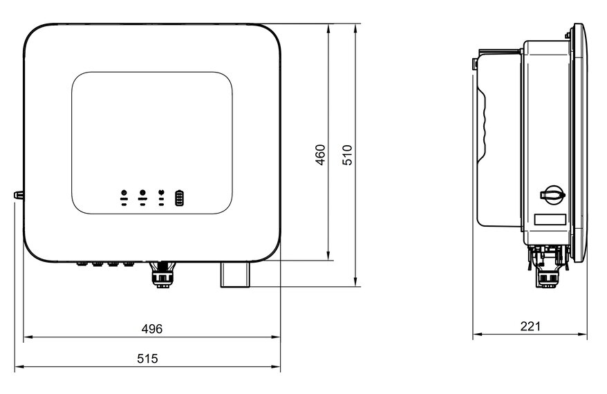
Width | Depth | Height |
497 mm | 221 mm | 461 mm |
497 mm | 221 mm | 461 mm |
497 mm | 221 mm | 461 mm |
Weight |
23 kg |
25 kg |
25 kg |
|
Topology |
non-isolated |
non-isolated |
non-isolated |
|
*also in parallel mains operation
3.3. Technical data — Heckert Solar EMS box
| Description | Value/dimension |
|---|---|
DC operating voltage |
224 V to 672 V |
Max. current (battery) |
50 A |
Operating temperature |
-10 °C to 50 °C |
Protection specification |
IP55 (plugged) |
Input voltage |
100 V to 240 V/1.8 A/50 Hz to 60 Hz |
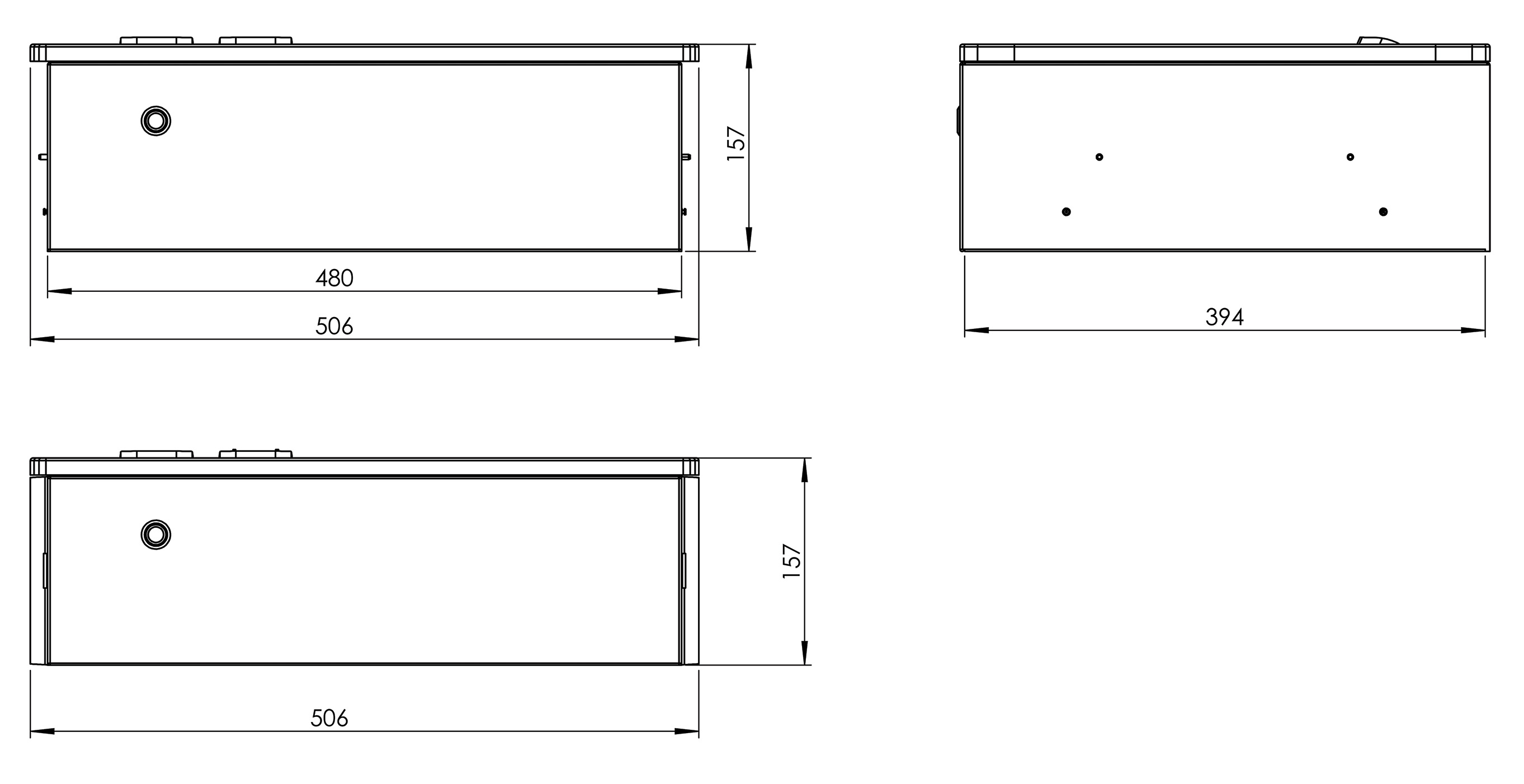
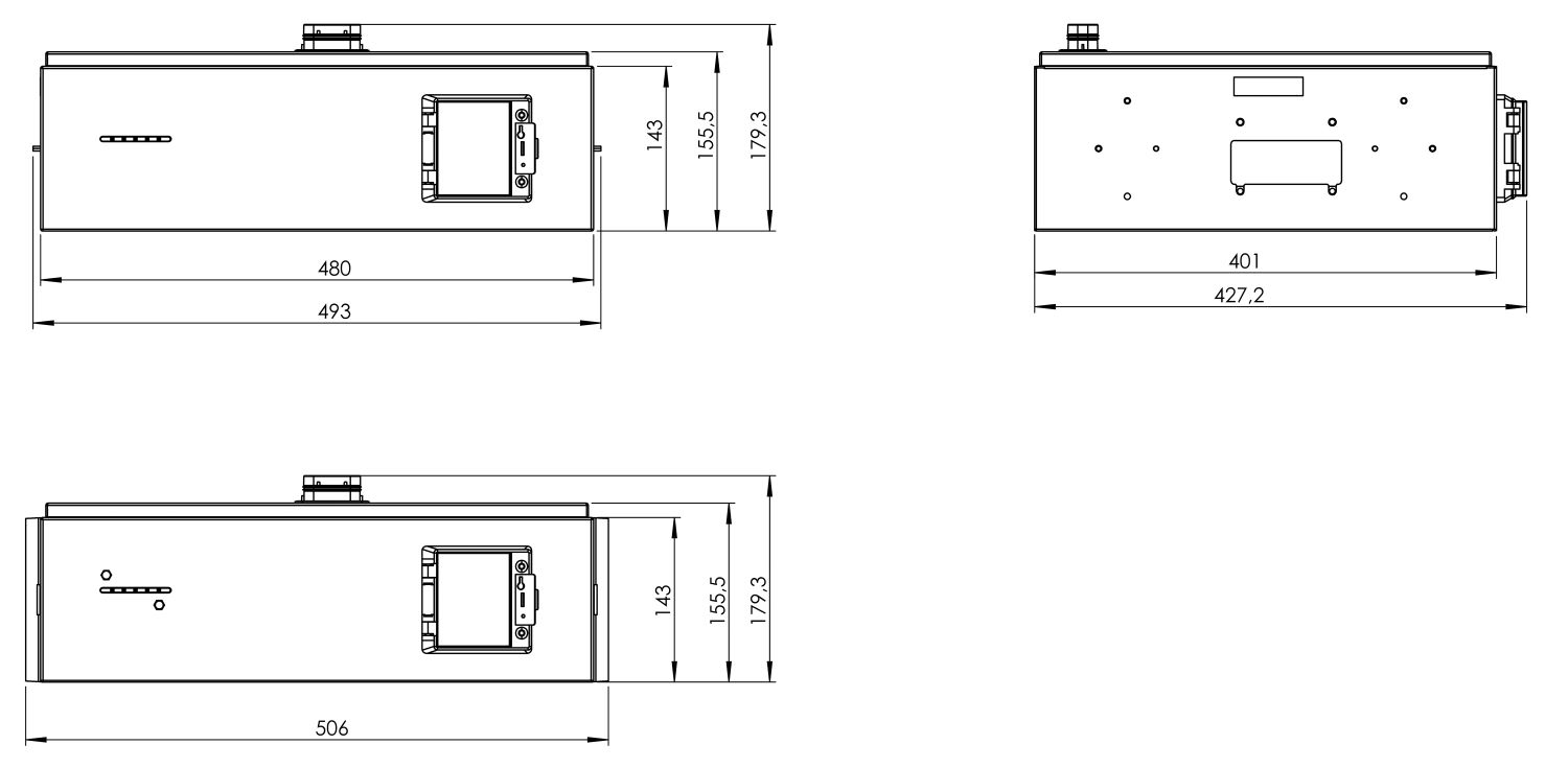
Width | Depth | Height |
506 mm | 401 mm | 157 mm |
Weight |
12 kg |
Installation |
stackable |
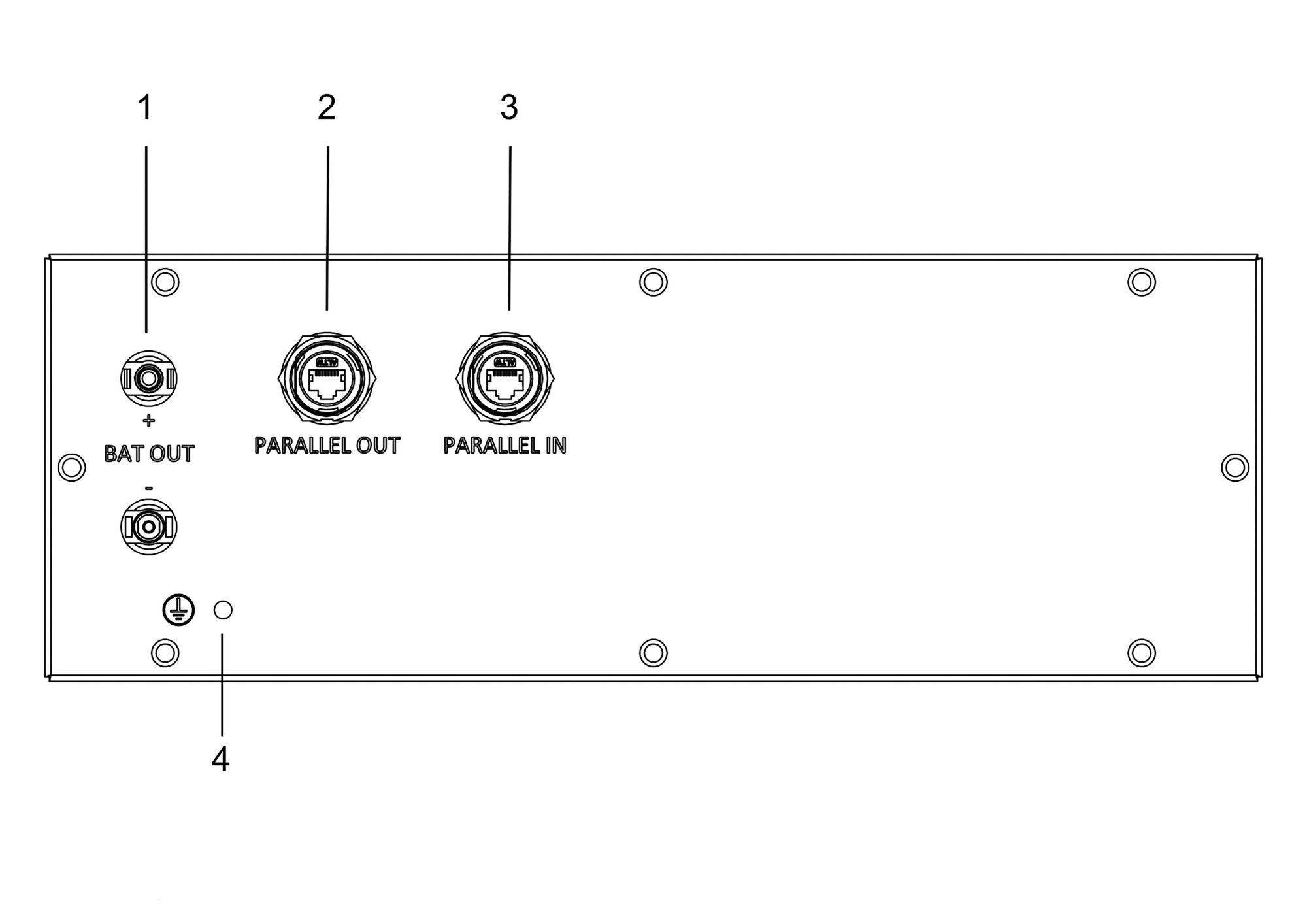
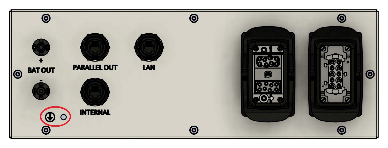
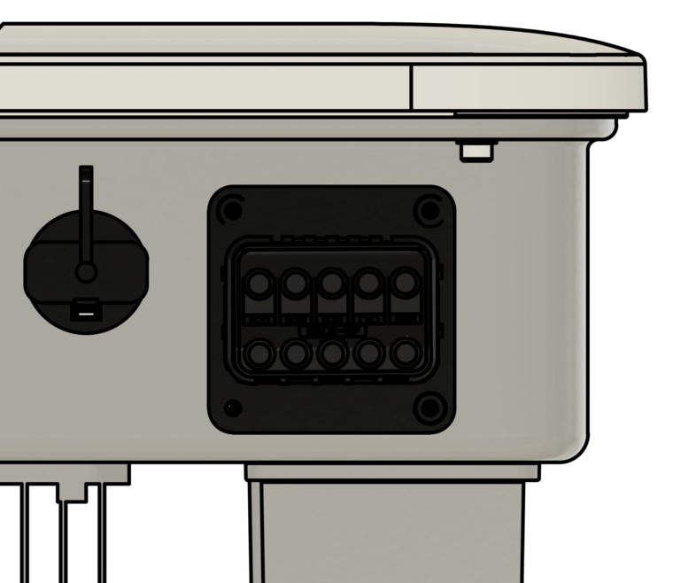
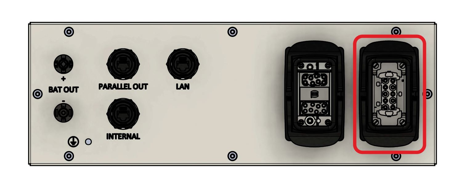
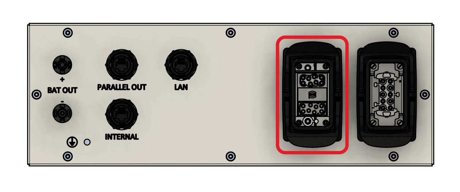
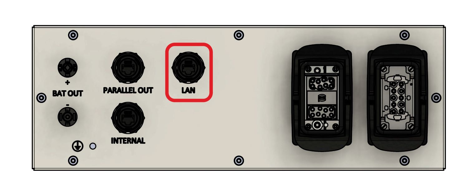
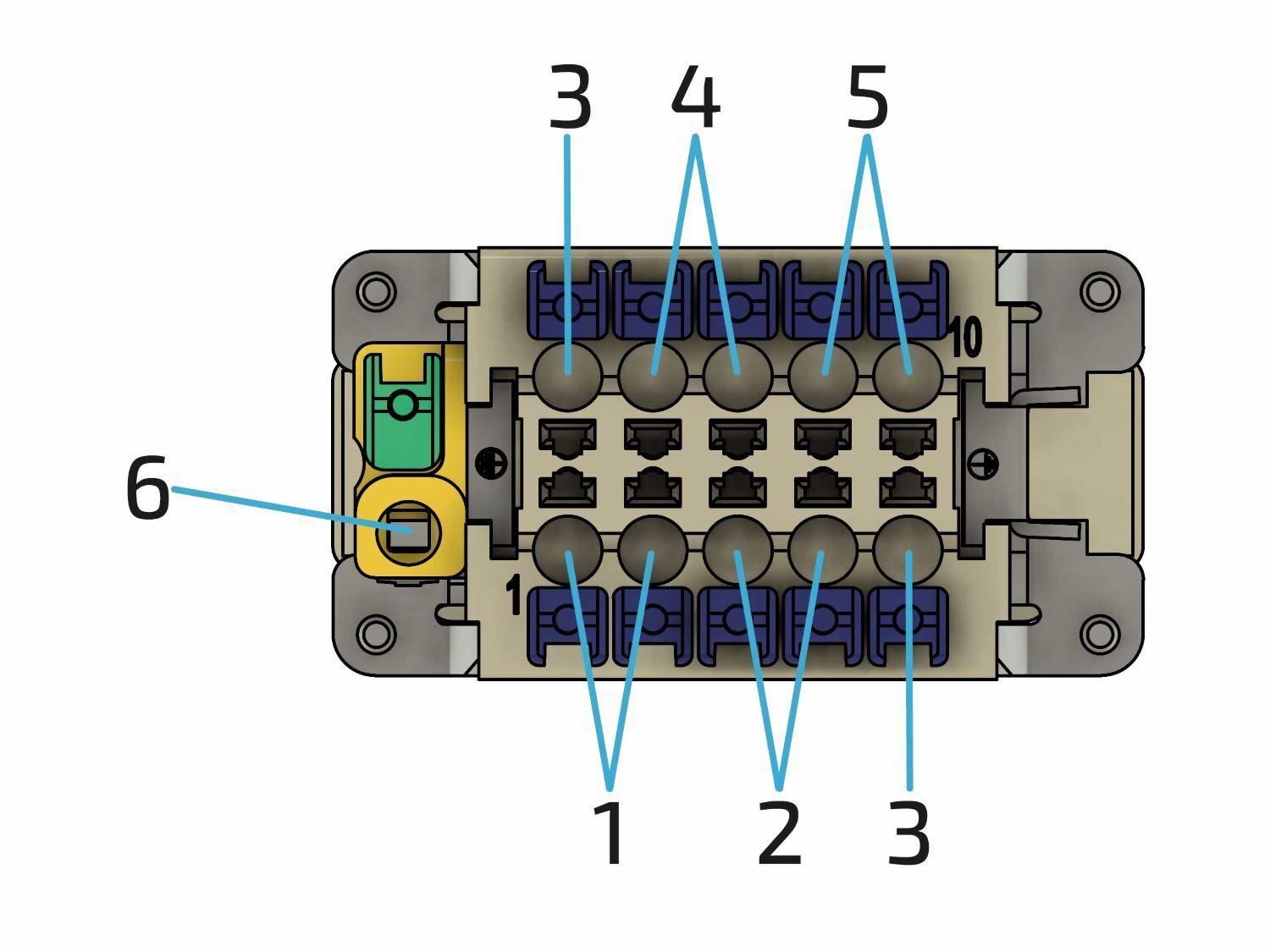
3.3.2. EMS box — Pin assignment
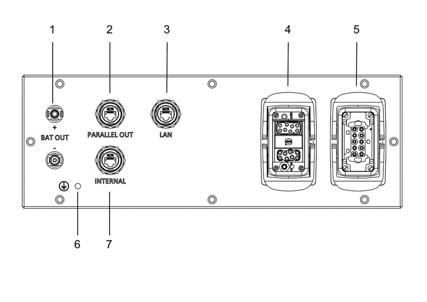
| Item | Description |
|---|---|
1 |
Battery connection to the inverter (MC4-Evo stor) |
2 |
Communication output for parallel connection of several batteries |
3 |
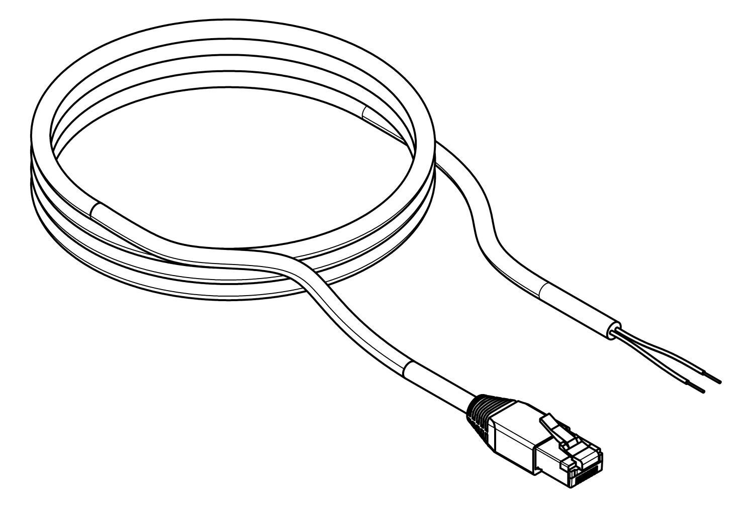
Customer network connection (LAN) RJ45 (network cable not included) |
4 |
Communication to the inverter, relay outputs; digital inputs (16-pin connector) |
5 |
Power supply EMS box; potential-free contacts (max. 10 A, measured) (10-pin plug) |
6 |
Earth connection |
7 |
For future applications (not assigned) |
3.4. Technical data — Heckert Solar parallel switch box (optional)
| Description | Value/dimension |
|---|---|
DC operating voltage |
224 V to 672 V |
Max. current (battery) |
50 A |
Operating temperature |
-10 °C ~ 50 °C |
Protection specification |
IP55 (plugged in) |
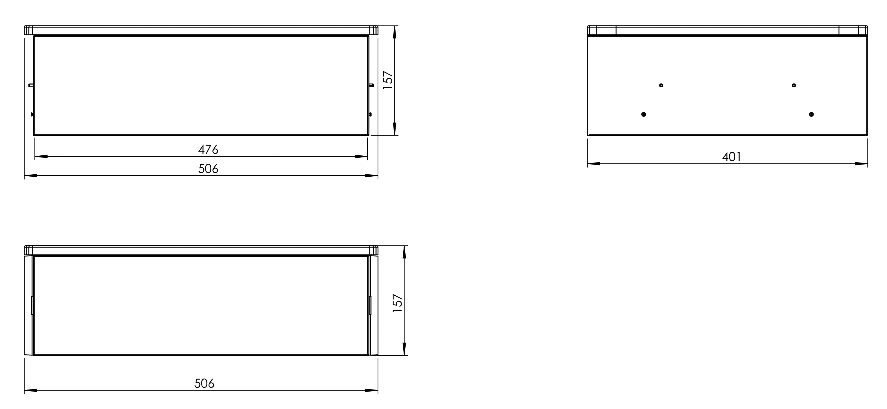
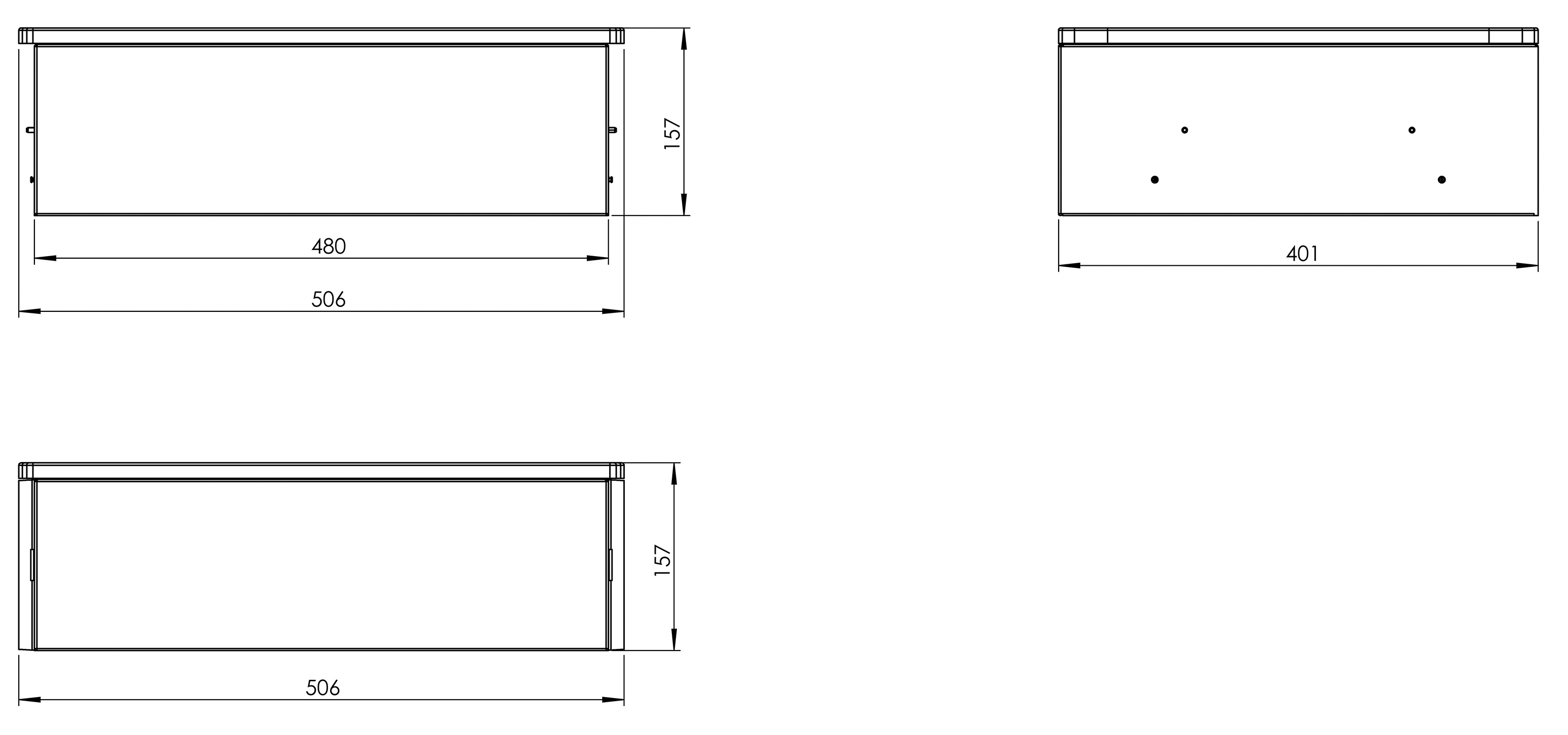
Width | Depth | Height |
506 mm |401 mm |157 mm |
Weight |
10 kg |
Installation |
stackable |
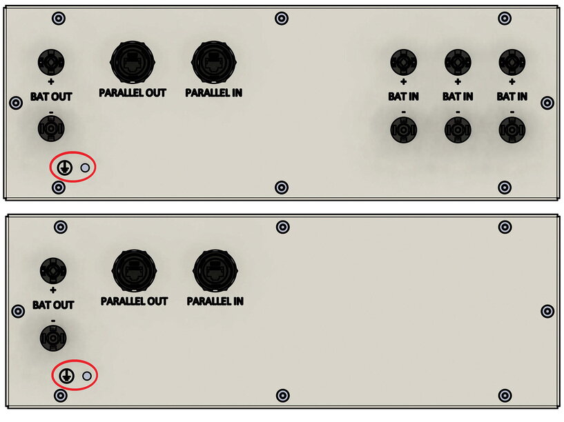
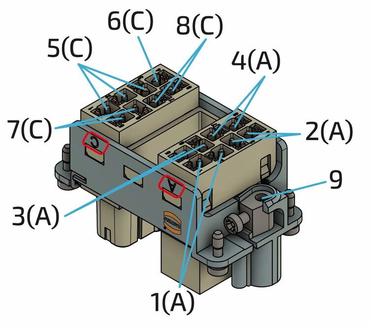
3.4.2. Parallel switch box — Terminal assignment
| Item | Description |
|---|---|
1 |
Battery connection to the inverter (MC4-Evo stor) |
2 |
Communication output for parallel connection of several battery towers |
3 |
Communication input for parallel connection of several battery towers |
4 |
Battery connection for additional battery towers (MC4-Evo stor) |
5 |
Earthing connection |
3.5. Technical data — Heckert Solar Extension box (optional)
| Description | Value/dimension |
|---|---|
DC operating voltage |
224 V to 672 V |
Max. current (battery) |
50 A |
Operating temperature |
-10 °C ~ 50 °C |
Protection specification |
IP55 (plugged in) |
Width | Depth | Height |
506 mm | 401 mm | 157 mm |
Weight |
9 kg |
Installation |
stackable |
3.5.2. Extension box — Pin assignment
| Item | Description |
|---|---|
1 |
Battery connection to EMS box in parallel (MC4-Evo stor) |
2 |
Communication output for parallel connection of several battery towers |
3 |
Communication input for parallel connection of several battery towers |
4 |
Earthing connection |
3.6. Technical data — Heckert Solar BMS box
| Description | Value/dimension |
|---|---|
Maximum operating voltage range |
224 V to 672 V |
Maximum output/input current |
50 A |
Optimal operating temperature |
15 °C to 30 °C |
Operating temperature range |
-20 °C to 55 °C |
Protection specification |
IP55 (plugged in) |
Width (incl. side panel) | Depth | Height |
506 mm |401 mm |143 mm |
Weight |
13 kg |
Installation |
stackable/wall mounting |
3.7. Technical data — Heckert Solar battery module
| Description | Value/dimension |
|---|---|
Usable capacity |
62.4 Ah/2.80 kWh |
Rated voltage |
44.8 V |
Output voltage range |
39.2 V to 50.4 V |
Battery operating temperature range |
-20 °C to +55 °C |
Storage temperature range (over 7 days) |
-30 °C to +60 °C |
Storage temperature range (over 30 days) |
-20 °C to +55 °C |
Storage temperature range (cumulative up to 270 days) |
-10 °C to +45 °C |
Protection specification |
IP55 (plugged) |
Weight |
30 kg |
Installation |
stackable |
Parallel connection |
4 battery towers in parallel |
Cooling |
Natural cooling |
Shipping capacity |
< 30 % SoC |
Module safety certification |
VDE 2510/IEC62619 |
UN transportation test standard |
UN38.3 |
Relative humidity during storage |
5 % to 95 % |
|
Storage longer than 12 months |
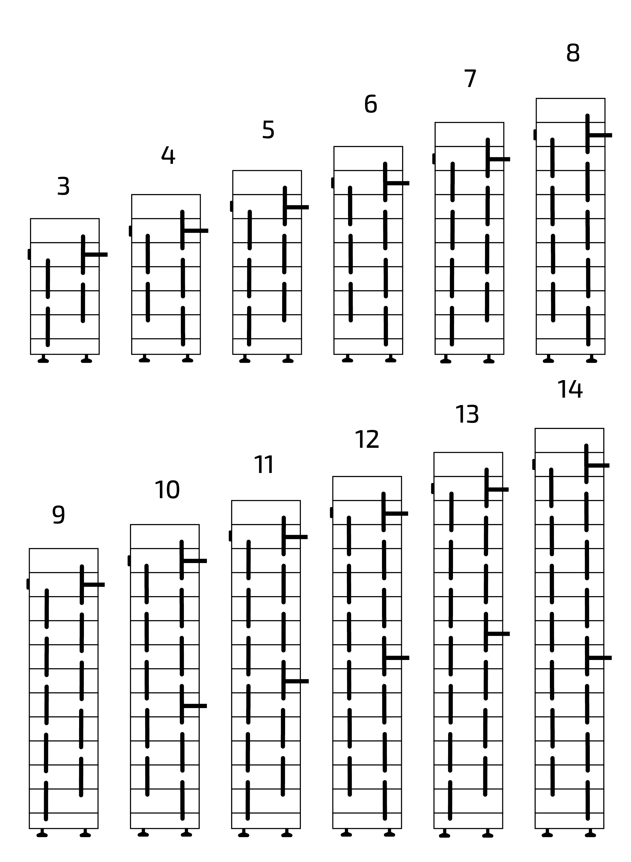
3.7.2. Electrical parameters of the battery modules
For 3 to 6 battery modules
Parameters |
Value/dimension |
|||
No. of modules |
3S |
4S |
5S |
6S |
Nominal capacity |
8.6 kWh |
11.4 kWh |
14.3 kWh |
17.2 kWh |
Width incl. side panel |
506 mm |
|||
Depth |
401 mm |
|||
Height |
834 mm |
977 mm |
1120 mm |
1263 mm |
Weight |
127 kg |
157 kg |
187 kg |
217 kg |
Nominal voltage |
134.4 V |
179.2 V |
224.0 V |
268,8 V |
Output voltage range |
117.6 V ~ 151.2 V |
156.8 V ~ 201.6 V |
196 V ~ 252 V |
235.2 V ~ 302.4 V |
Maximum continuous charge/discharge power |
6.72 kW |
8.96 kW |
11.20 kW |
13.44 kW |
For 8 to 11 battery modules
| Parameter | Value/dimension | |||
|---|---|---|---|---|
Module |
8S |
9S |
10S |
11S |
Nominal capacity |
22.9 kWh |
25.8 kWh |
28.7 kWh |
31.5 kWh |
Width incl. side panel |
506 mm |
|||
Depth |
401 mm |
|||
Height |
1549 mm |
1692 mm |
1835 mm |
1978 mm |
Weight |
277 kg |
307 kg |
337 kg |
367 kg |
Rated voltage |
358.4 V |
403.2 V |
448.0 V |
492.8 V |
Output voltage range |
313.6 V ~ 403.2 V |
352.8 V ~ 453.6 V |
392.0 V ~ 504.0 V |
431.2 V ~ 554.4 V |
Maximum continuous charging/discharging power |
17.92 kW |
20.16 kW |
22.40 kW |
24.64 kW |
For 12 to 14 battery modules
| Parameter | Value/dimension | ||
|---|---|---|---|
Module |
12S |
13S |
14S |
Nominal capacity |
34.4 kWh |
37.3 kWh |
40.1 kWh |
Width incl. side panel |
506 mm |
||
Depth |
401 mm |
||
Height |
2121 mm |
2264 mm |
2407 mm |
Weight |
397 kg |
427 kg |
457 kg |
Rated voltage |
537.6 V |
582.4 V |
627.2 V |
Output voltage range |
470.4 V ~ 604.8 V |
509.6 V ~ 655.2 V |
548.8 V ~ 705.6 V |
Maximum continuous charging/discharging power |
26.88 kW |
29.12 kW |
30.00 kW |
4. Allgemeine Beschreibung
Symphon-E 6, 10 & 15 is an emergency-power-capable electrical energy storage system that can build its own household power grid. Lithium iron phosphate batteries (LiFePO4) are used in this modular system for storing electrical energy.
4.1. Erklärung der "Notstromfunktion"
Home 10; Home 6, 10 & 15; Home 20 & 30
Der Heckert Solar Hybrid-Wechselrichter der Serie:
-
FHI-10-DAH, FHI-10-DAH 16A, FHI-20-DAH, FHI-29,9-DAH
-
FINV-6-2-DAH, FINV-10-2-DAH, FINV-15-2-DAH
verfügt über einen zusätzlichen Ausgang für notstrombefähigte Verbraucher. Bei Netzausfall trennt der Wechselrichter die zwei Ausgänge allpolig voneinander, wobei N und PE am Notstromausgang gebrückt werden. Die gesamte Umschaltmimik für Umschaltung in unter 10 ms ist im Wechselrichter integriert.
Beim Notstromnetz handelt es sich um echten Drehstrom mit 100 % Schieflastfähigkeit und einer leicht erhöhten Frequenz, für eine einfache Synchronisation bei Netzwiederkehr. Ist Spannungsgleichheit bei Netzwiederkehr auf allen Phasen gegeben, findet die Umschaltung zum Netzparallelbetrieb wieder innerhalb von wenigen Millisekunden statt. Das Notstromnetz kann ausschließlich bei ausreichendem Ladezustand der Batterie aufrechterhalten werden. Ist das nicht gegeben, wird die Batterie aus den angeschlossenen PV-Strings geladen, bevor das Notstromnetz schwarzgestartet werden kann.
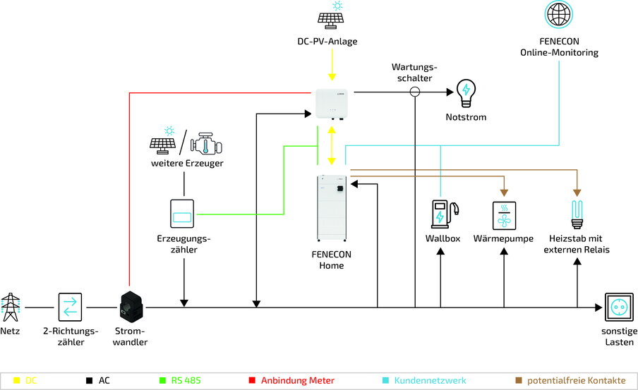
4.2. System configuration — General overview
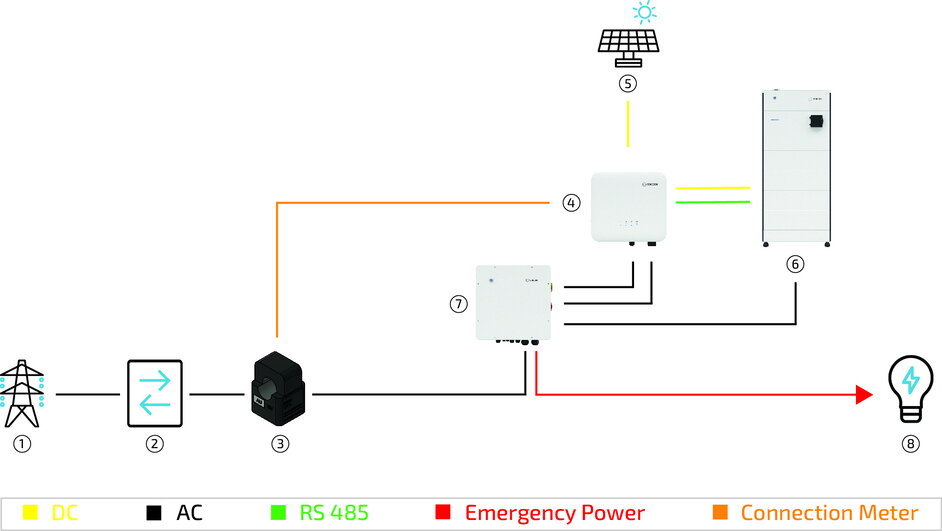
4.3. System structure: Variants with emergency power
4.3.1. Standard setup with emergency power
| Item | Description |
|---|---|
1 |
Grid |
2 |
Bi-directional meter |
3 |
Current transformer |
4 |
Inverter |
5 |
PV system |
6 |
Electrical energy storage |
7 |
Load(s) (supplied with emergency power) |
8 |
Load(s) (not supplied with emergency power) |
|
Within the emergency power function, the inverter acts as its own grid former and sets up its own 3-phase system for the separate emergency power branch (see Technical data). Compared to the public grid system, the grid shape of the emergency power mode has a lower "buffer effect" with regard to load peaks, starting currents, DC components and strongly fluctuating loads. Due to the limited power of the inverter, such loads are only possible within certain limits. The manufacturer is not responsible for the domestic installation. |
4.3.2. System structure with additional PV generator
| Item | Description |
|---|---|
1 |
Grid |
2 |
Bi-directional meter |
3 |
Current transformer |
4 |
3-phase sensor or with PV-Inverter app |
5 |
PV inverter |
6 |
Additional PV system |
7 |
Electrical energy storage |
8 |
PV system |
9 |
Inverter |
10 |
Load(s) (supplied with emergency power) |
11 |
Load(s) (not supplied with emergency power) |
4.3.3. System structure as an AC system
| Item | Description |
|---|---|
1 |
Grid |
2 |
Bi-directional meter |
3 |
Current transformer |
4 |
3-phase sensor or with PV Inverter app |
5 |
PV inverter |
6 |
PV system |
7 |
Electrical energy storage |
8 |
Inverter |
9 |
Load(s) (supplied with emergency power) |
10 |
Load(s) (not supplied with emergency power) |
4.3.4. System with manual emergency power changeover
| Item | Description |
|---|---|
1 |
Grid |
2 |
Bi-directional meter |
3 |
Current transformer |
4 |
Inverter |
5 |
PV system |
6 |
Electrical energy storage |
7 |
Manual emergency power switch |
8 |
Load(s) (supplied with emergency power) |
4.3.5. System setup with automatic off-grid switch (Heckert Solar AVU) — Heckert Solar Home 6 & 10
| Pos. | Beschreibung |
|---|---|
1 |
Netz |
2 |
2-Richtungszähler |
3 |
Smartmeter |
4 |
Wechselrichter |
5 |
PV-Anlage |
6 |
Heckert Solar Home 6 oder Home 10 |
7 |
Automatische Verbraucher-Umschaltung (AVU) * |
8 |
Verbraucher |
|
The automatic off-grid switch is only compatible with Home 6 and Home 10 systems. |
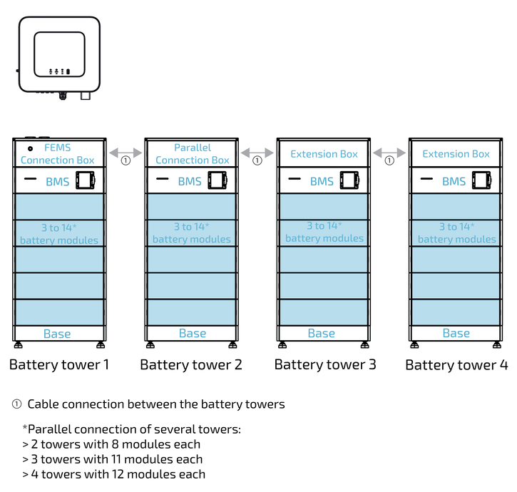
4.3.6. Required components
Depending on the system configuration, a maximum of the following components is required. When connecting up to four battery towers in parallel, ensure that the same number of battery modules is installed in each battery tower.
Number of battery towers |
Number of battery modules max. |
BMS box |
EMS box |
Parallel switch box |
Extension box |
1 |
14 |
1 |
1 |
- |
- |
2 |
28 |
1 |
1 |
1 |
- |
3 |
42 |
1 |
1 |
1 |
1 |
4 |
56 |
1 |
1 |
1 |
2 |
5. Assembly preparation
5.1. Scope of delivery
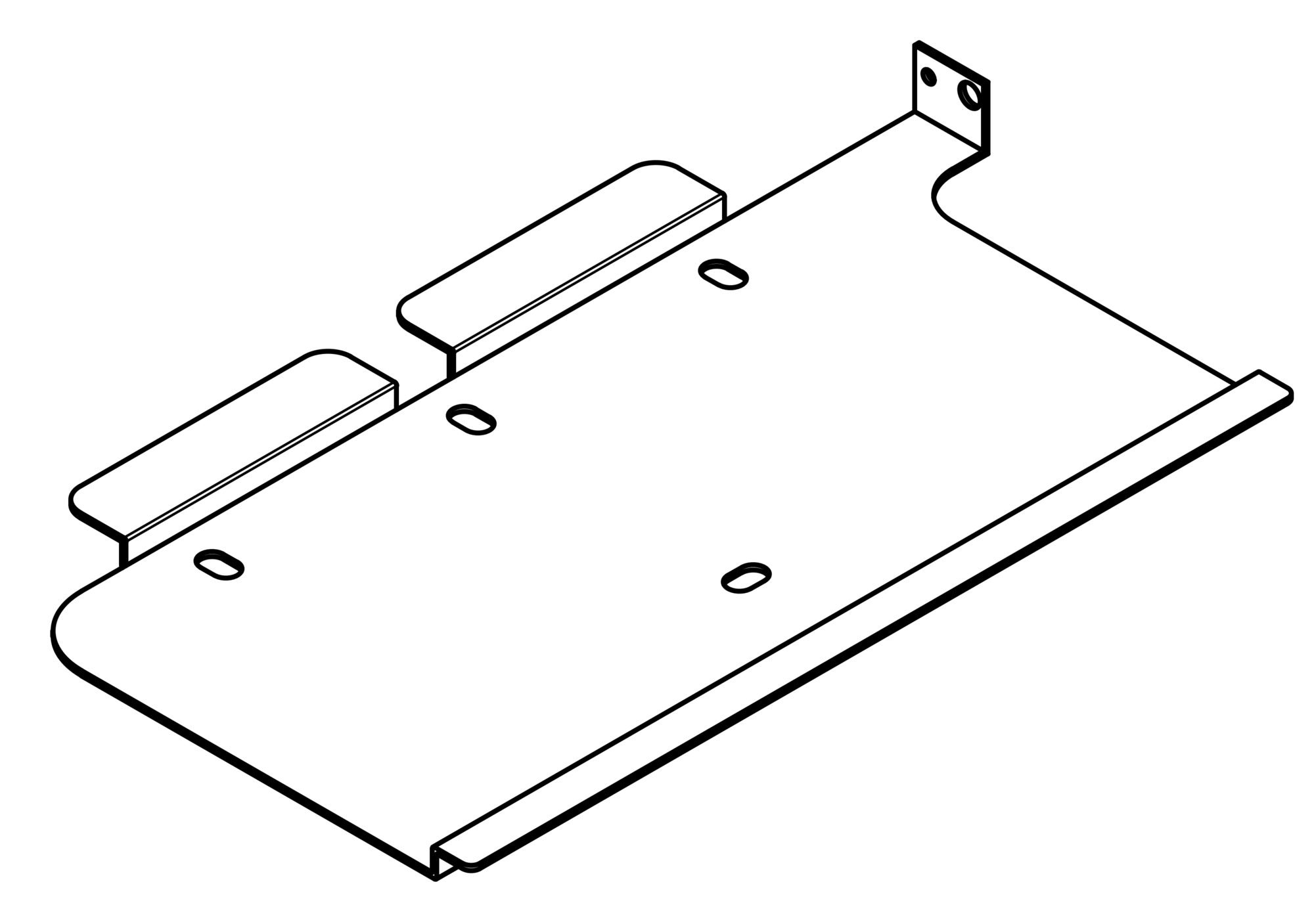
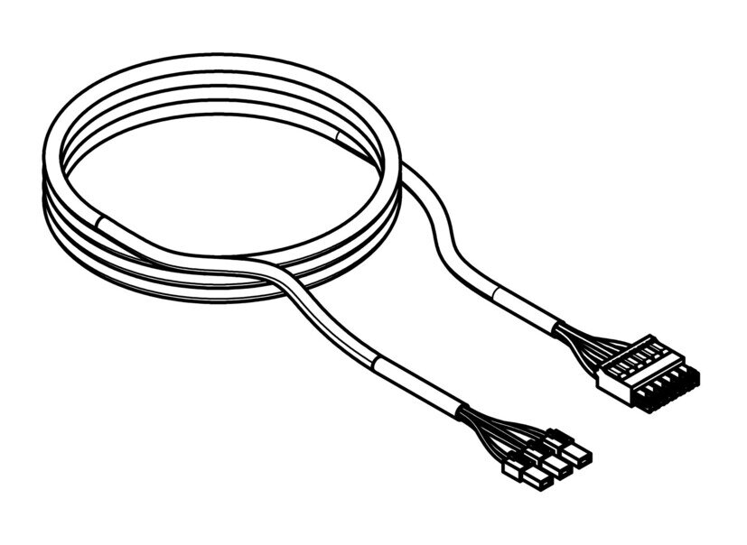
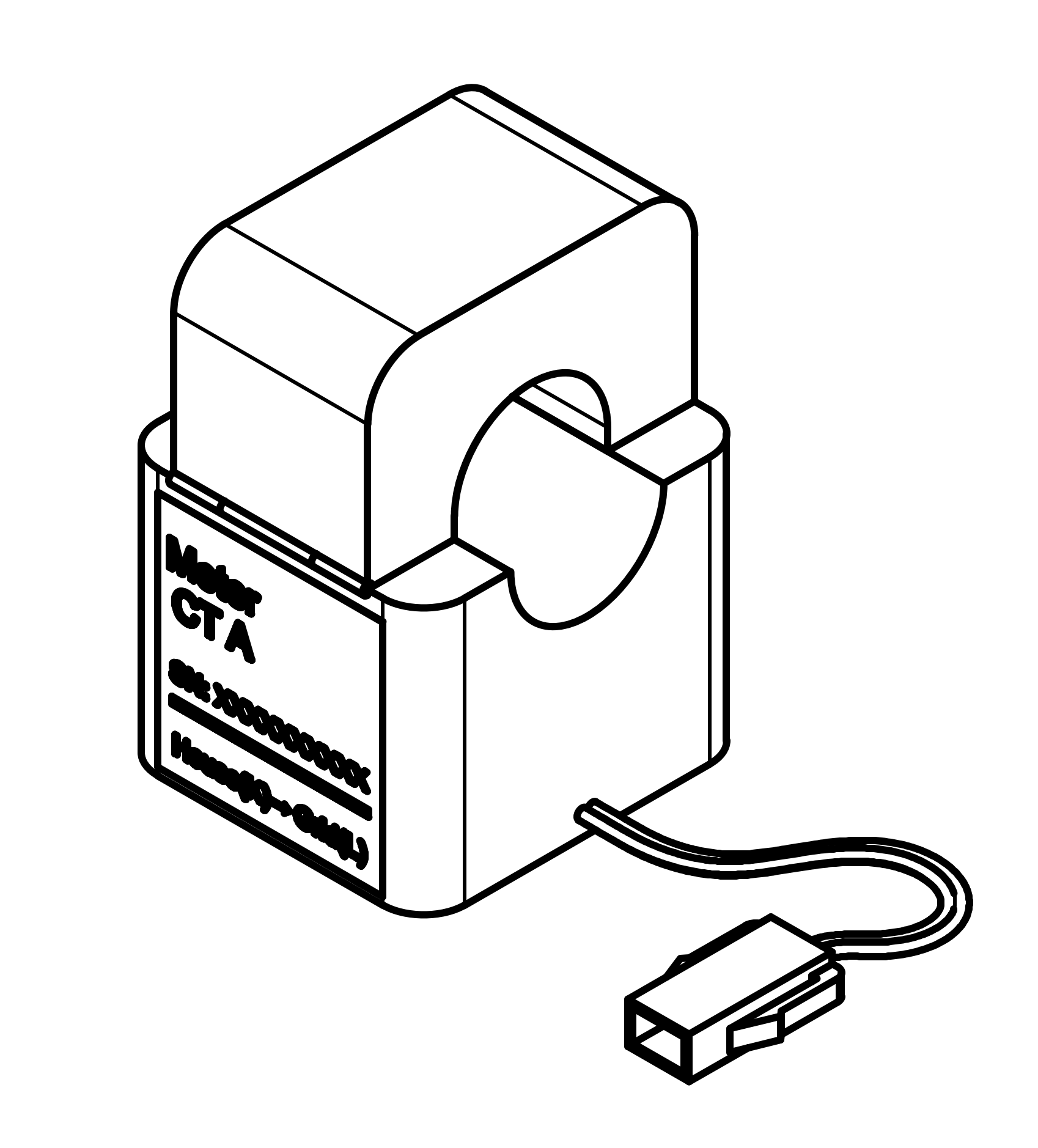
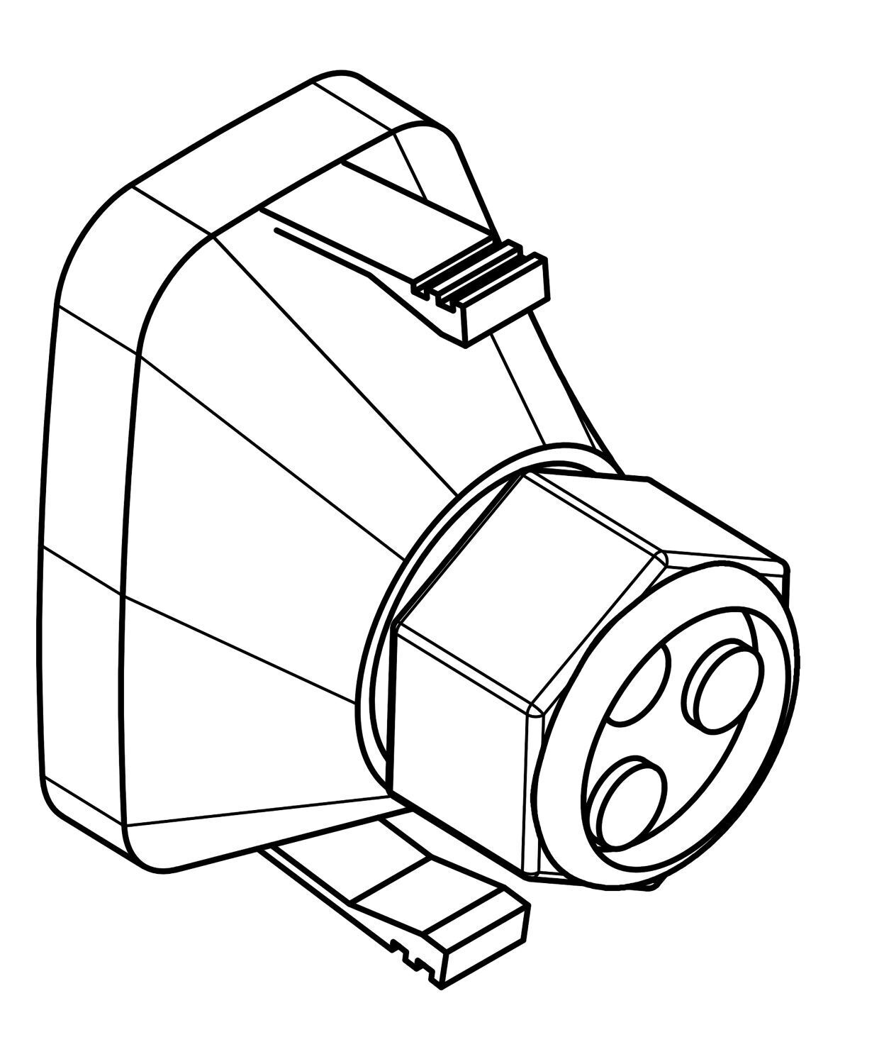
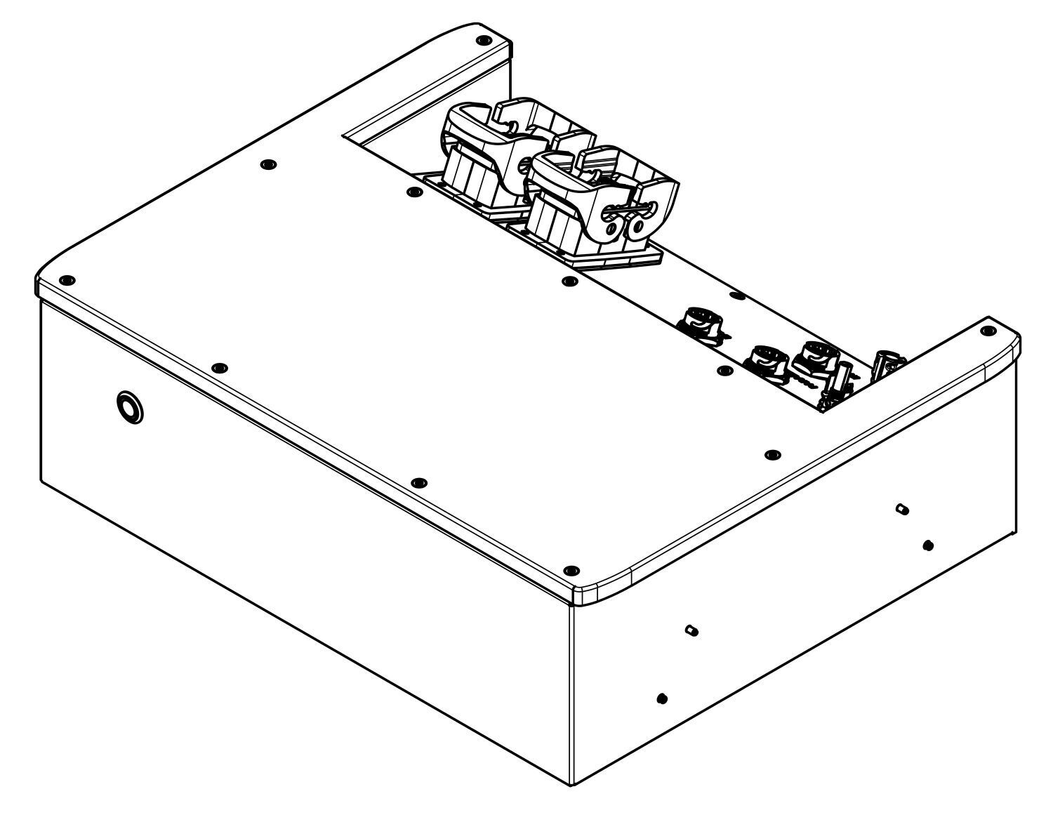
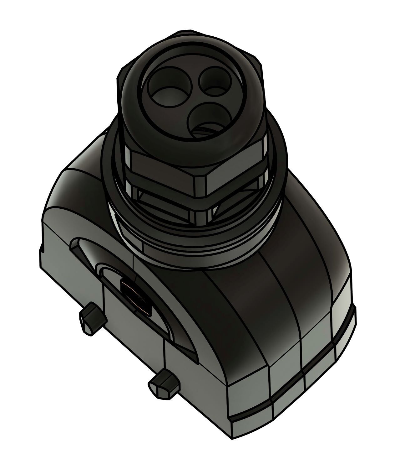
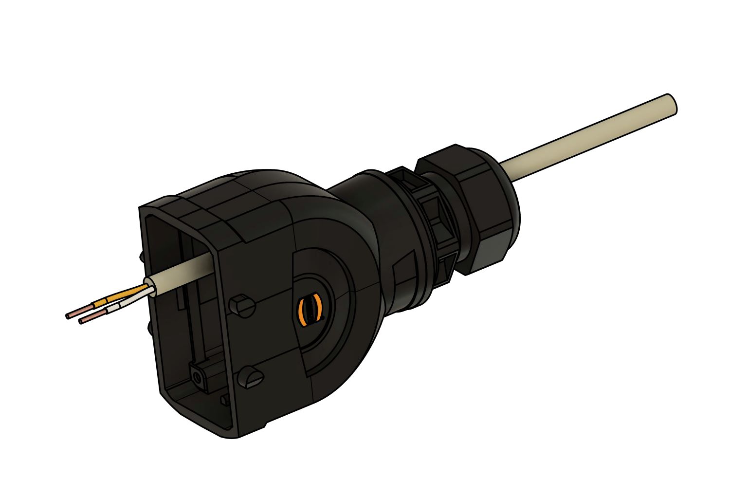
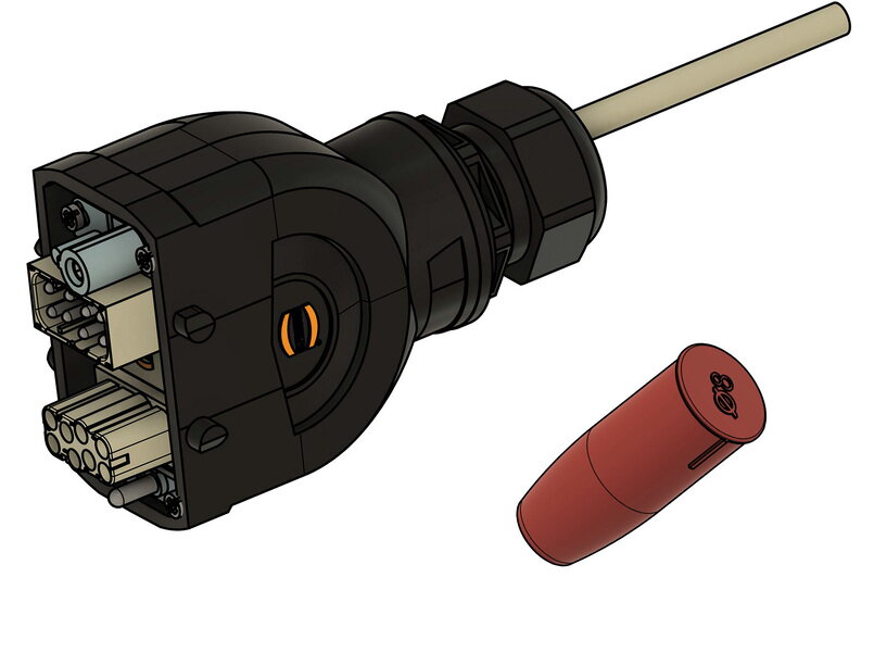
5.1.1. Symphon-E 6, 10 & 15-Inverter — Variants A & B
|
Es sind zwei Varianten des Wechselrichters im Umlauf. Die Funktionen und technischen Daten der beiden Varianten sind exakt gleich. Der Anschlussbereich der Kommunikationsleitungen und die Stromwandler unterscheiden sich hier minimal. Daher ist die Anleitung in den relevanten Abschnitten immer eine Variante A und eine Variante B aufgeführt. |
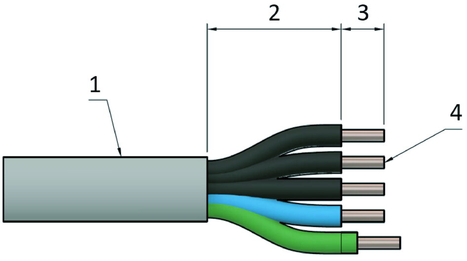
| illustration | number | designation |
|---|---|---|
|
1 |
Symphon-E 6, 10 & 15-Inverter |
|
2 |
Tools for PV and battery plugs |
|
1 |
Wall mount |
|
1 |
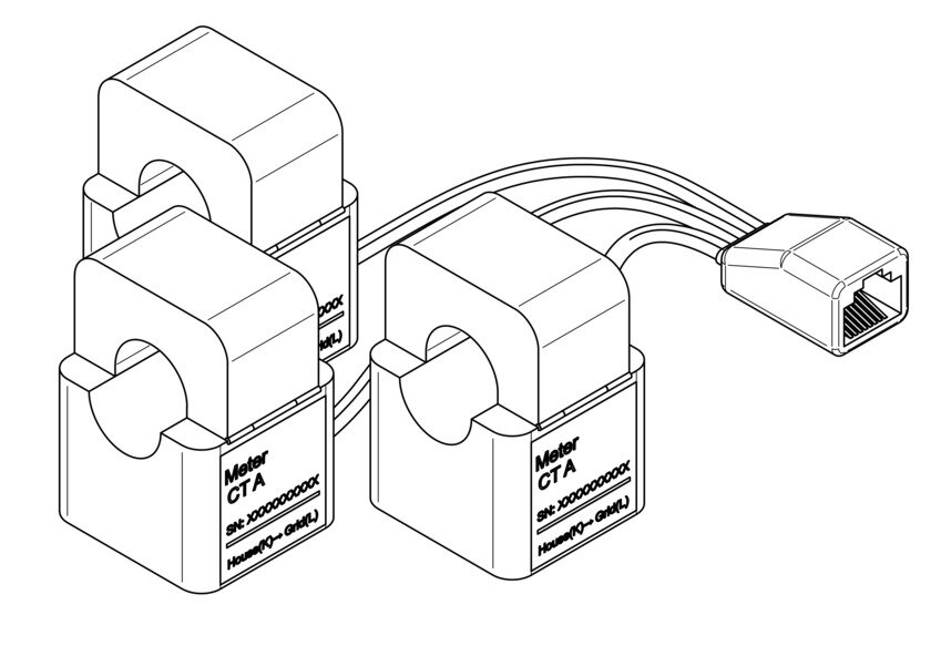
split-core CT communication cable |
|
3 |
split-core CT |
|
1 |
Communication port cover |
|
2(3) |
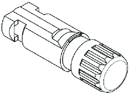
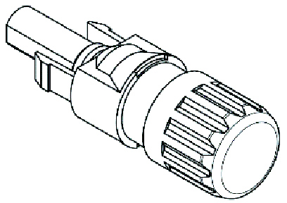
MC4 plug |
|
2(3) |
MC4 socket |
|
1 |
EMS-Cable |
|
1 |
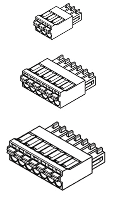
2-Pin-Push-In-Connector |
1 |
4-Pin-Push-In-Connector |
|
2 |
6-pin push-in connector |
|

|
1 |
PE cable lug |
|
4 |
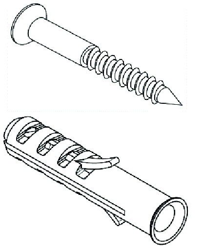
Screw with screw anchor |
|
1 |
Cover AC connection |
|
1 |
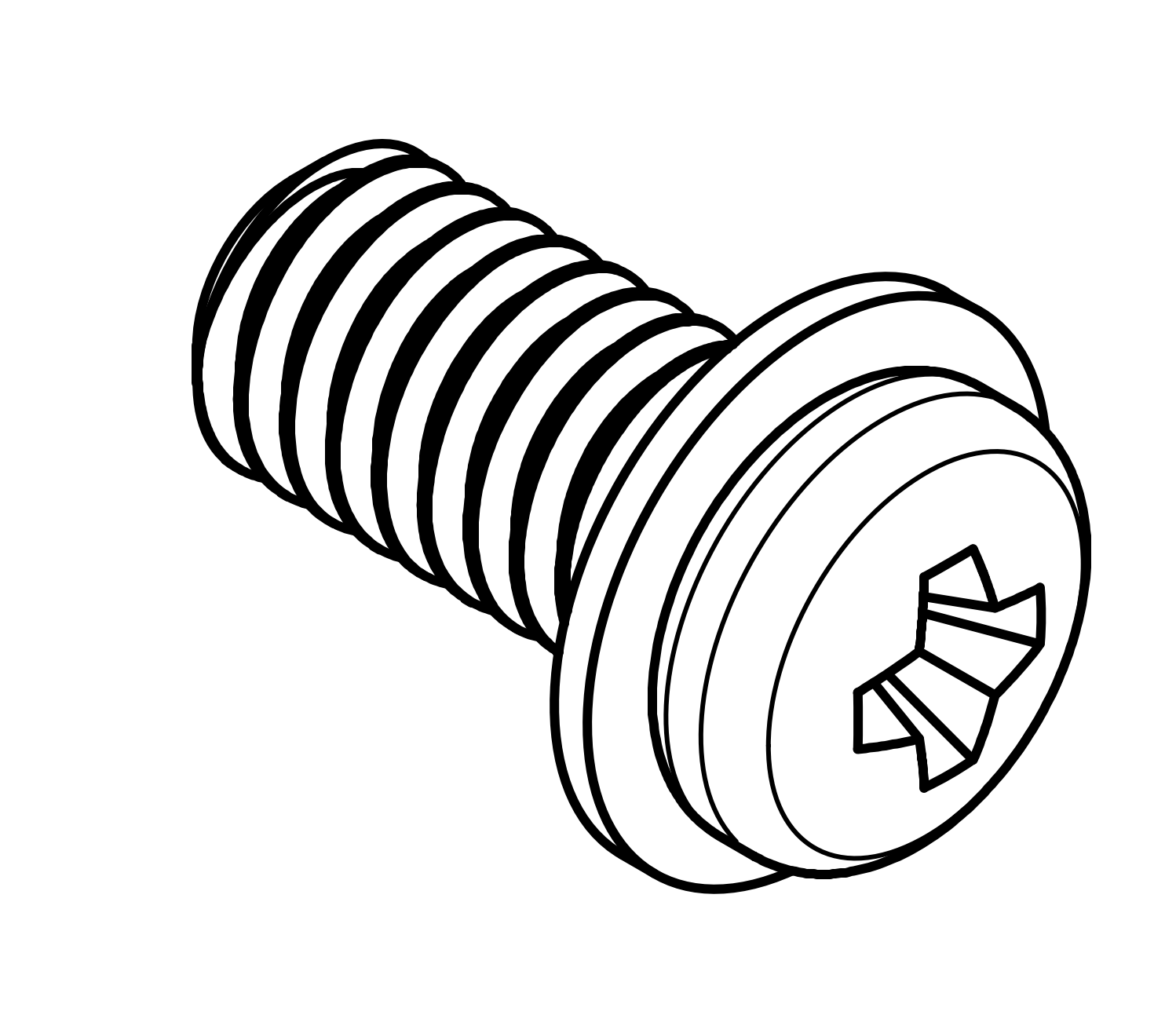
M5 screw for earthing |
| illustration | number | designation |
|---|---|---|
|
|
1 |
Symphon-E 6, 10 & 15-Inverter |
|
|
2 |
Tools for PV and battery plugs |
|
|
1 |
Wall mount |
|
1 |
Split-core CT |
|
|
1 |
Cover communication port |
|
|
2(3) |
MC4 plug |
|
|
2(3) |
MC4 socket |
|
|
1 |
EMS-Cable |
|
|
1 |
2-Pin-Push-In-Connector |
3 |
4-Pin-Push-In-Connector |
|
1 |
6-pin push-in connector |
|
|
|
1 |
PE cable lug |
|
|
4 |
Screw with screw anchor |
|
|
1 |
Cover AC connection |
|
|
1 |
M5 screw for earthing |
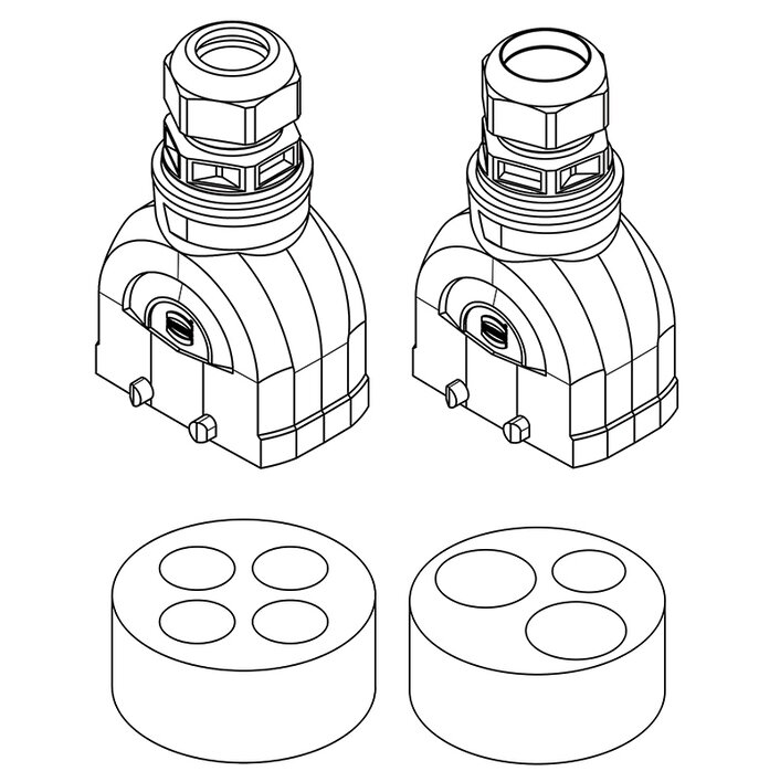
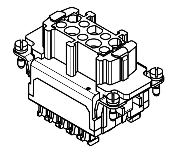
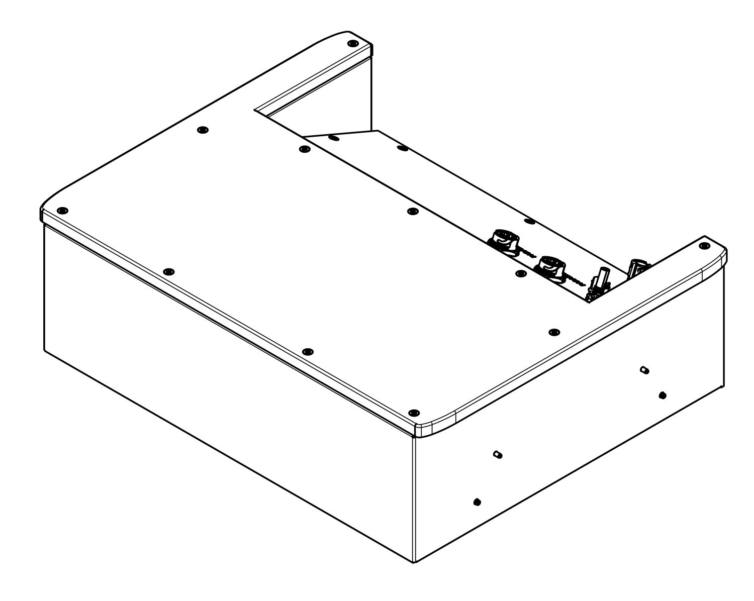
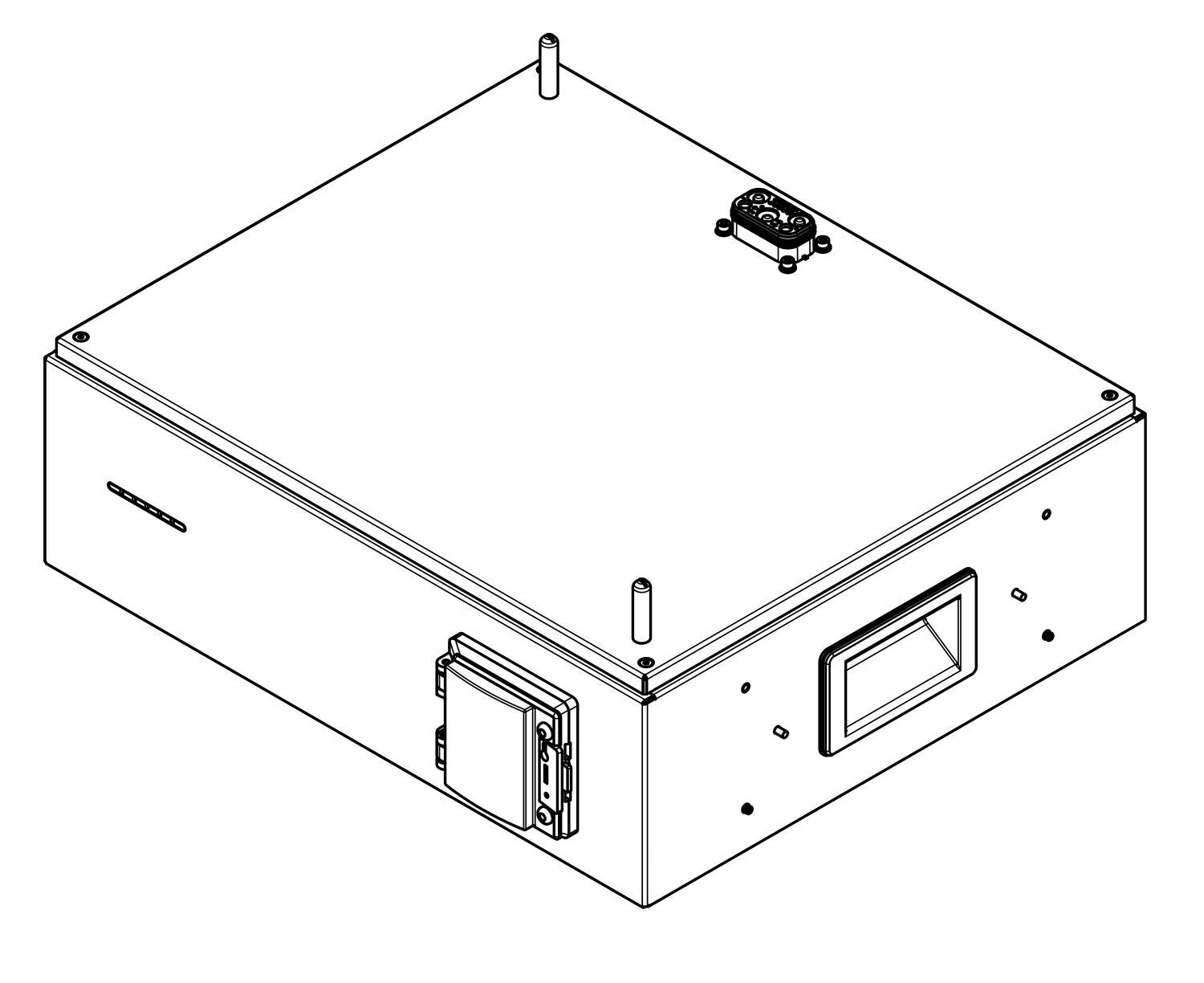
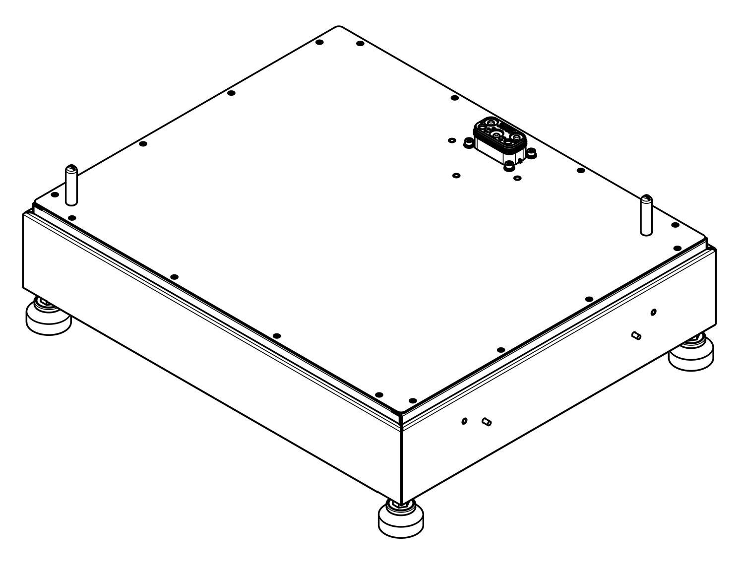
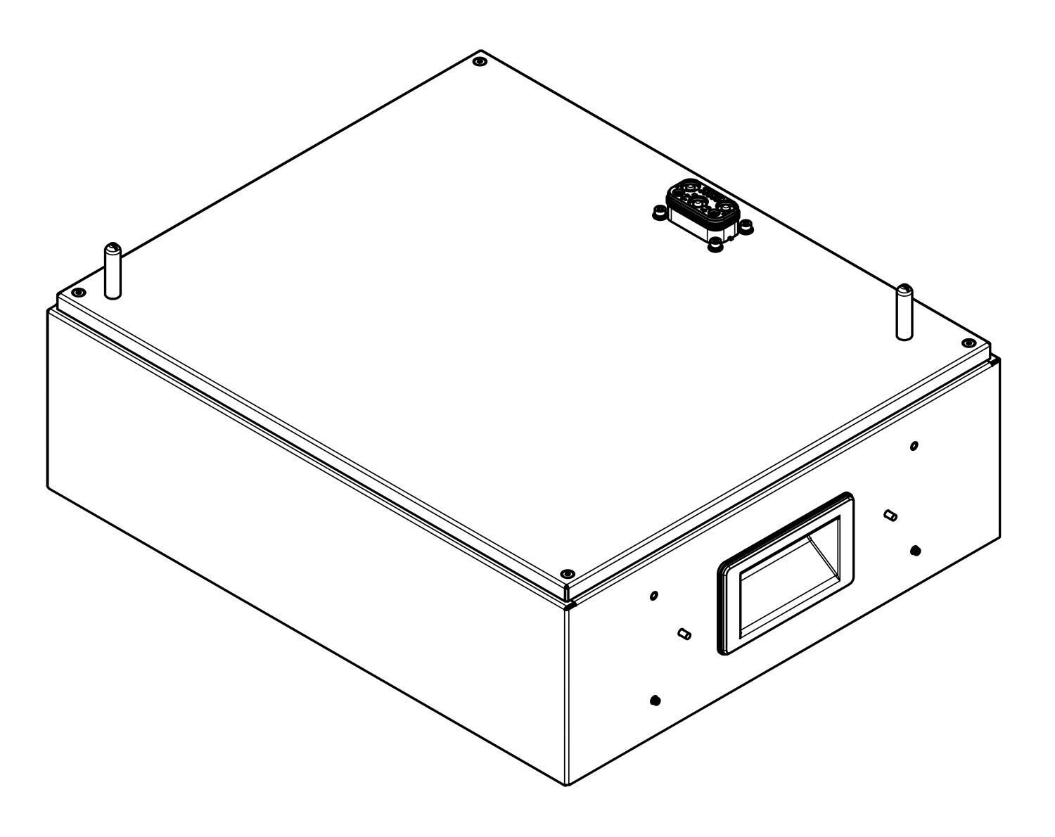
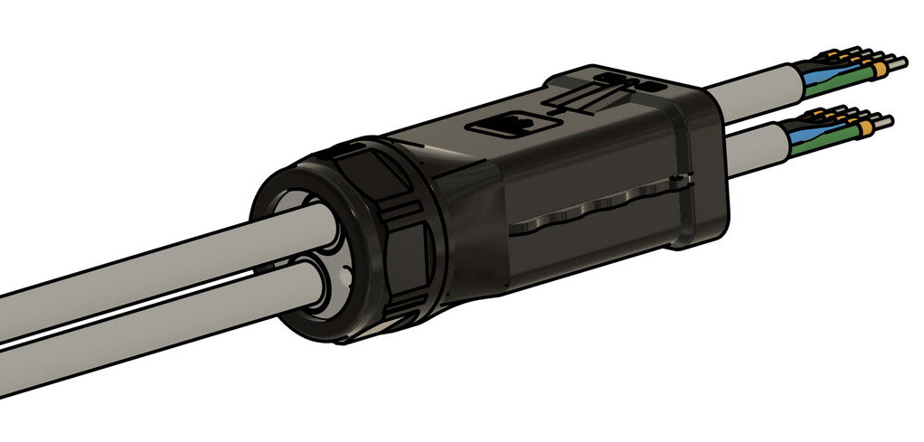
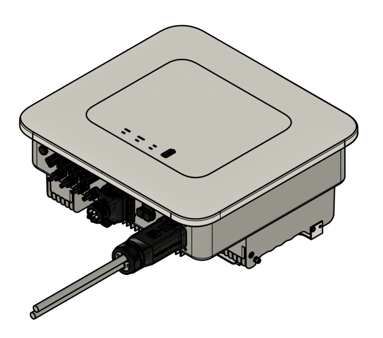
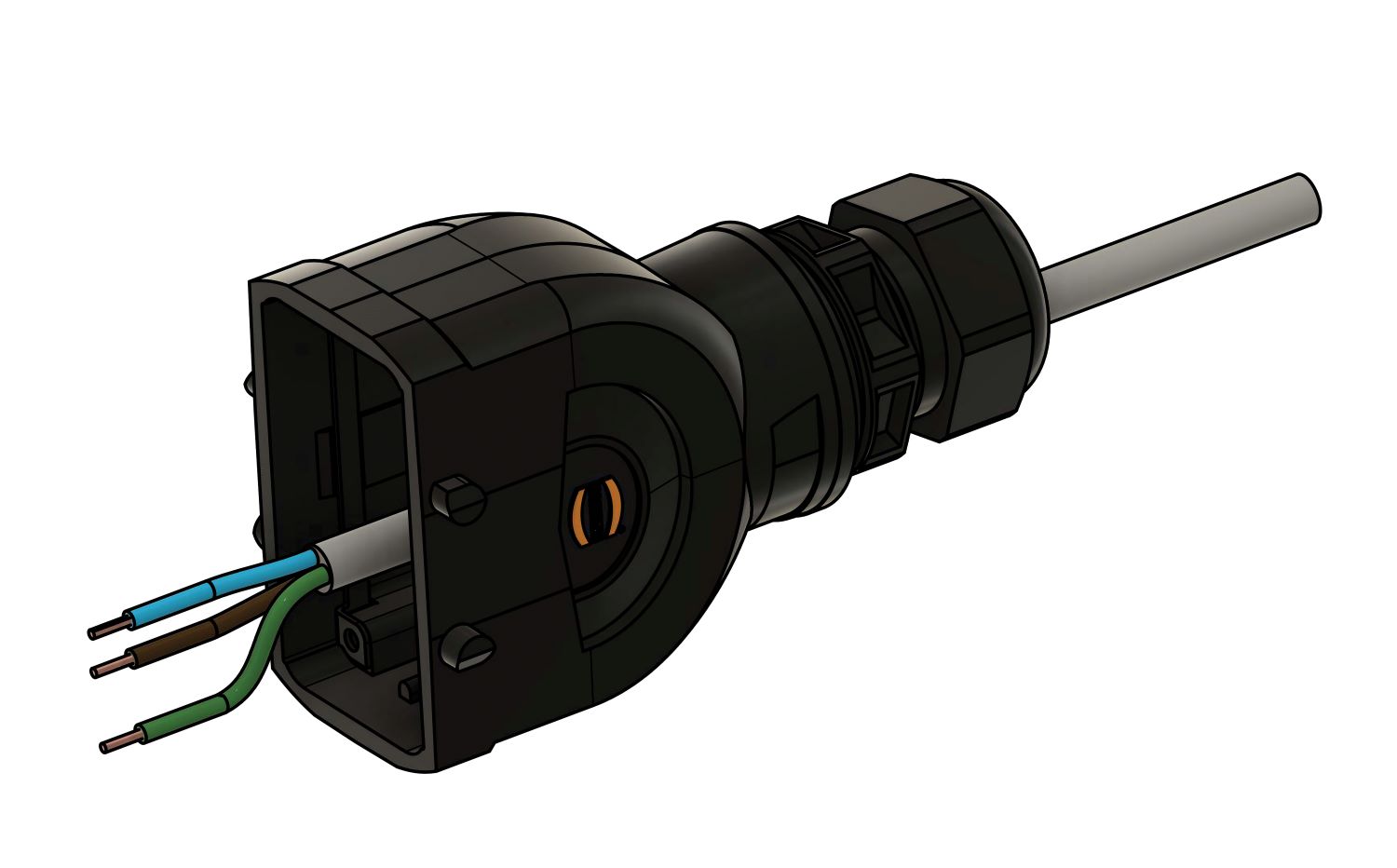
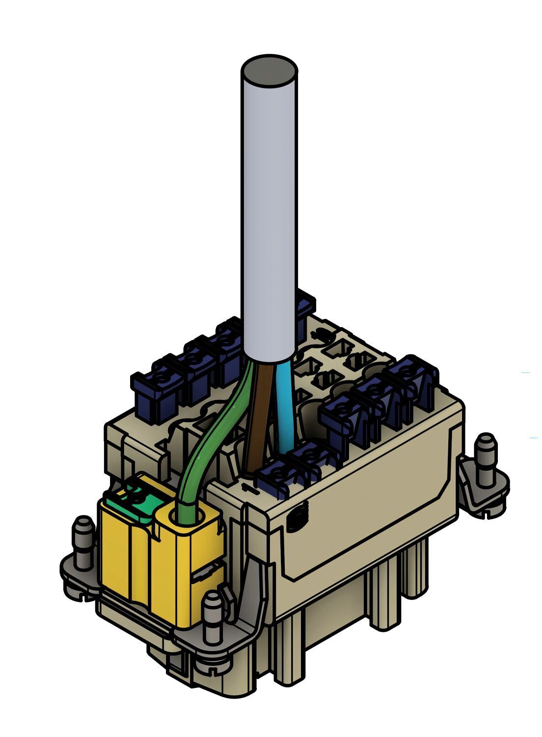
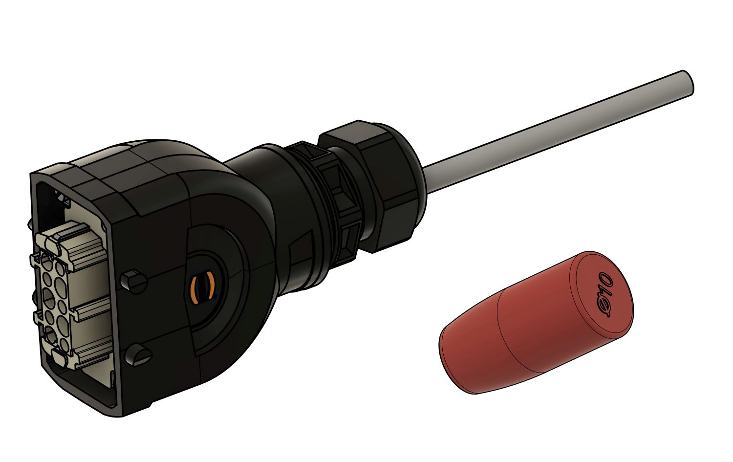
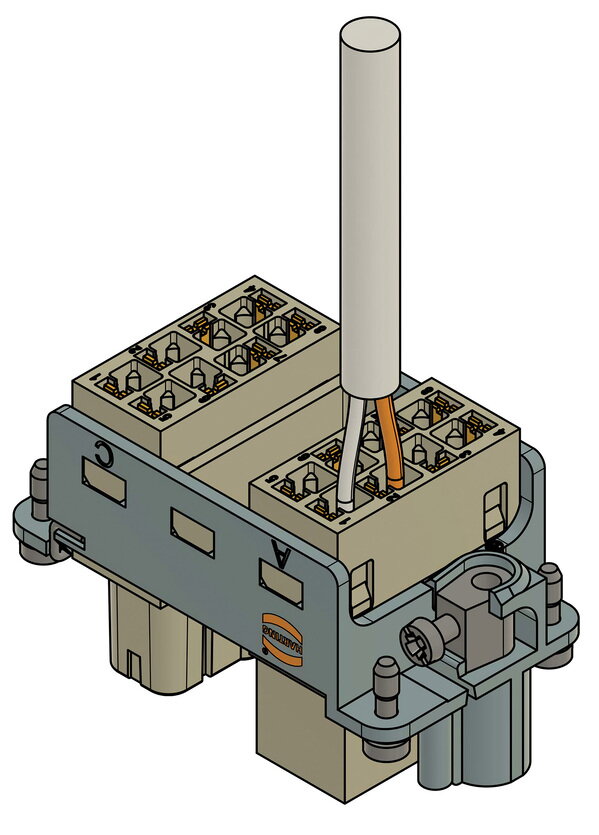
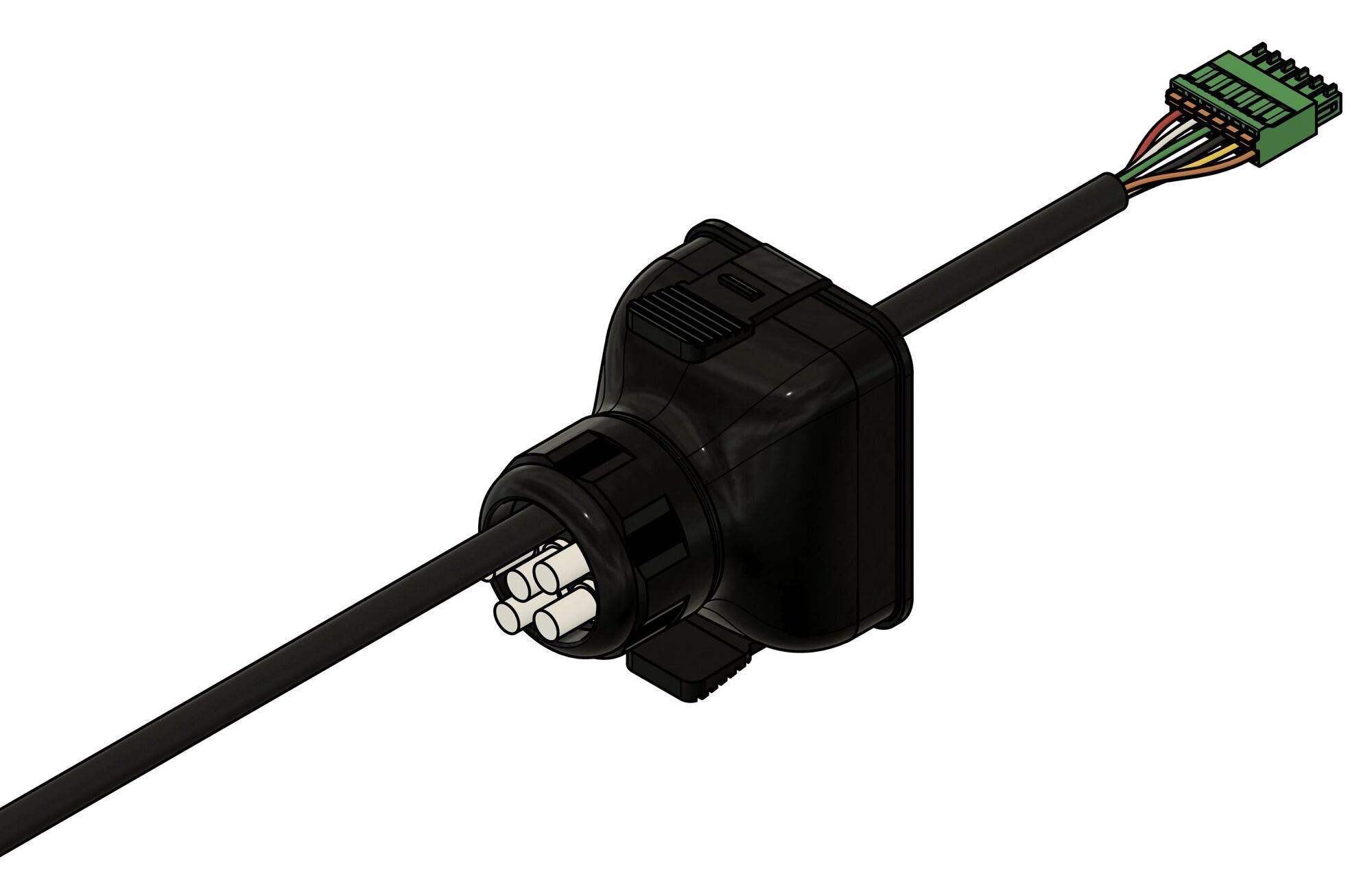
5.1.2. Heckert Solar EMS box
| illustration | number | designation |
|---|---|---|
|
1 |
Heckert Solar-EMS box |
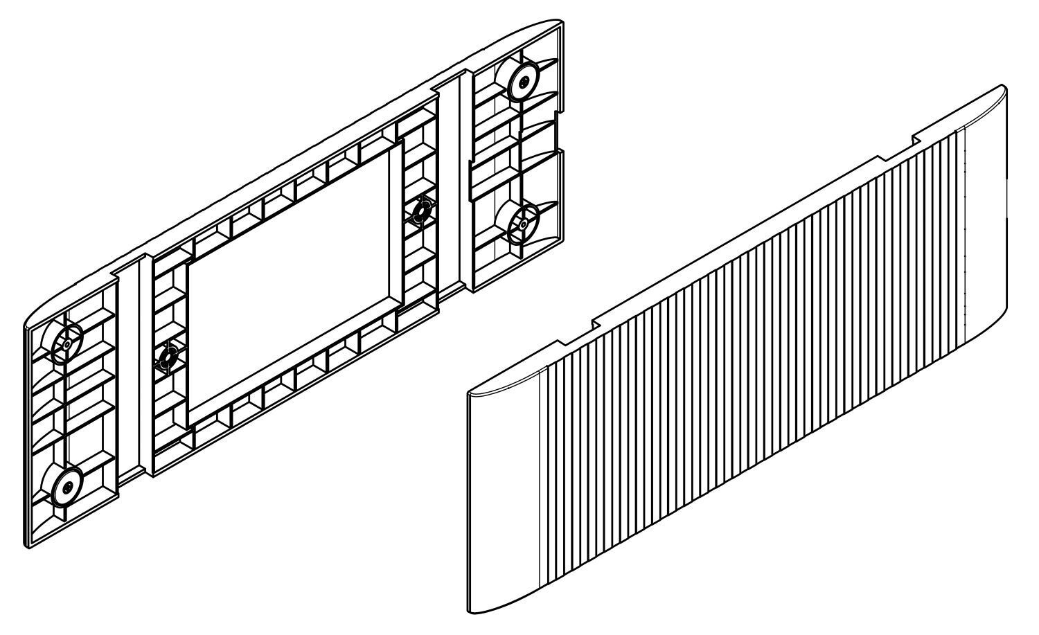
|
2 |
Side panel |
|
2 |
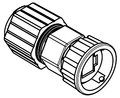
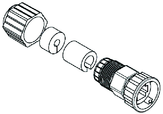
Harting housing with cable gland 13-21 mm, multi-hole seal 4 x 8mm |
|
1 |
Harting socket 10-pin |
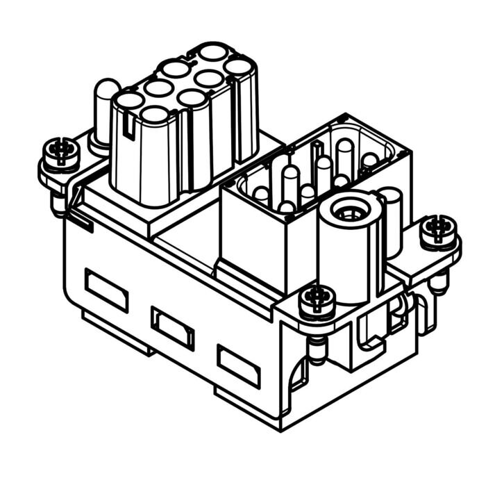
|
1 |
Harting insert 16-pin (assembled) |
|
1 |
Jumper plug |
|
2 |
Network connector housing |
|
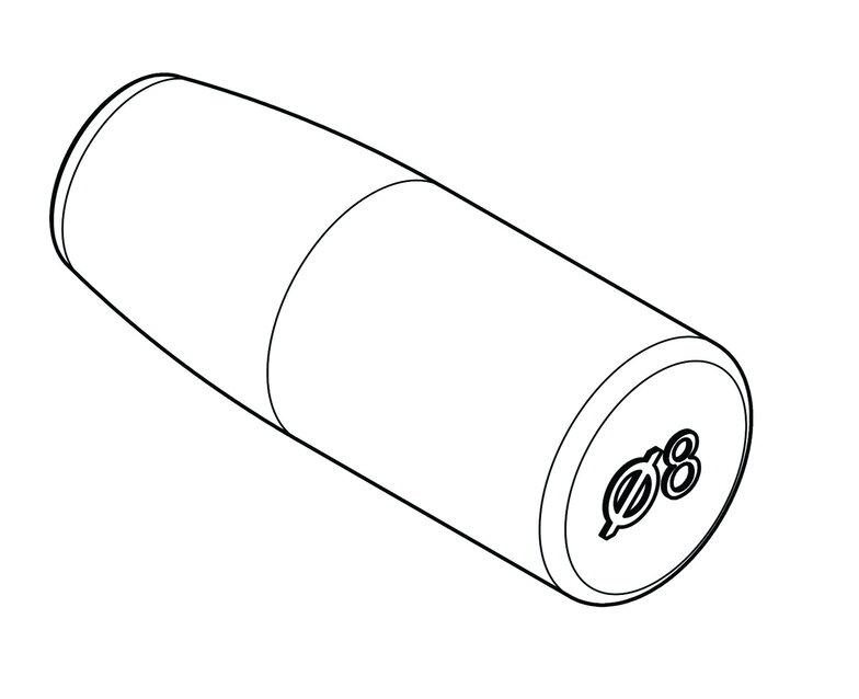
5 |
Filler plug, 8 mm |

|
2 |
Filler plug, 10 mm |
|
1 |
Battery cable set, 3 m |
|
1 |
Installation and service instructions (QR code) |
|
1 |
Operating instructions (for the end customer, |
|
|
1 |
Quick start guide |
5.1.3. Heckert Solar parallel switch box (optional)
| illustration | number | designation |
|---|---|---|
|
1 |
Heckert Solar-Parallel switch box |
|
|
2 |
Side panel |
|
|
2 |
Each set of two DC cables, 2 m |
|
1 |
Communication cable parallel connection, 2 m |
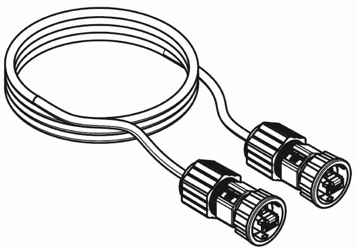
5.1.4. Heckert Solar — Extension box (optional)
| illustration | number | designation |
|---|---|---|
|
1 |
Heckert Solar-Extension box |
|
|
2 |
Side panel |
|
|
2 |
each set of two DC cables, 2 m |
|
|
1 |
Communication cable, 2 m |
5.1.5. Heckert Solar BMS box/base
| illustration | number | designation |
|---|---|---|
|
1 |
Heckert Solar-BMS box |
|
1 |
Base |
|
|
2 |
Side panel (Heckert Solar-BMS box) |
|
2 |
Side panel (base) |
|
4 |
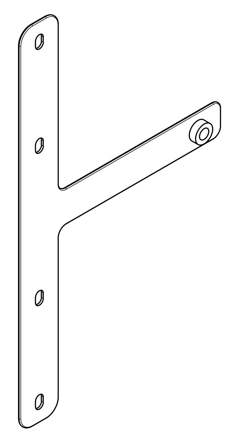
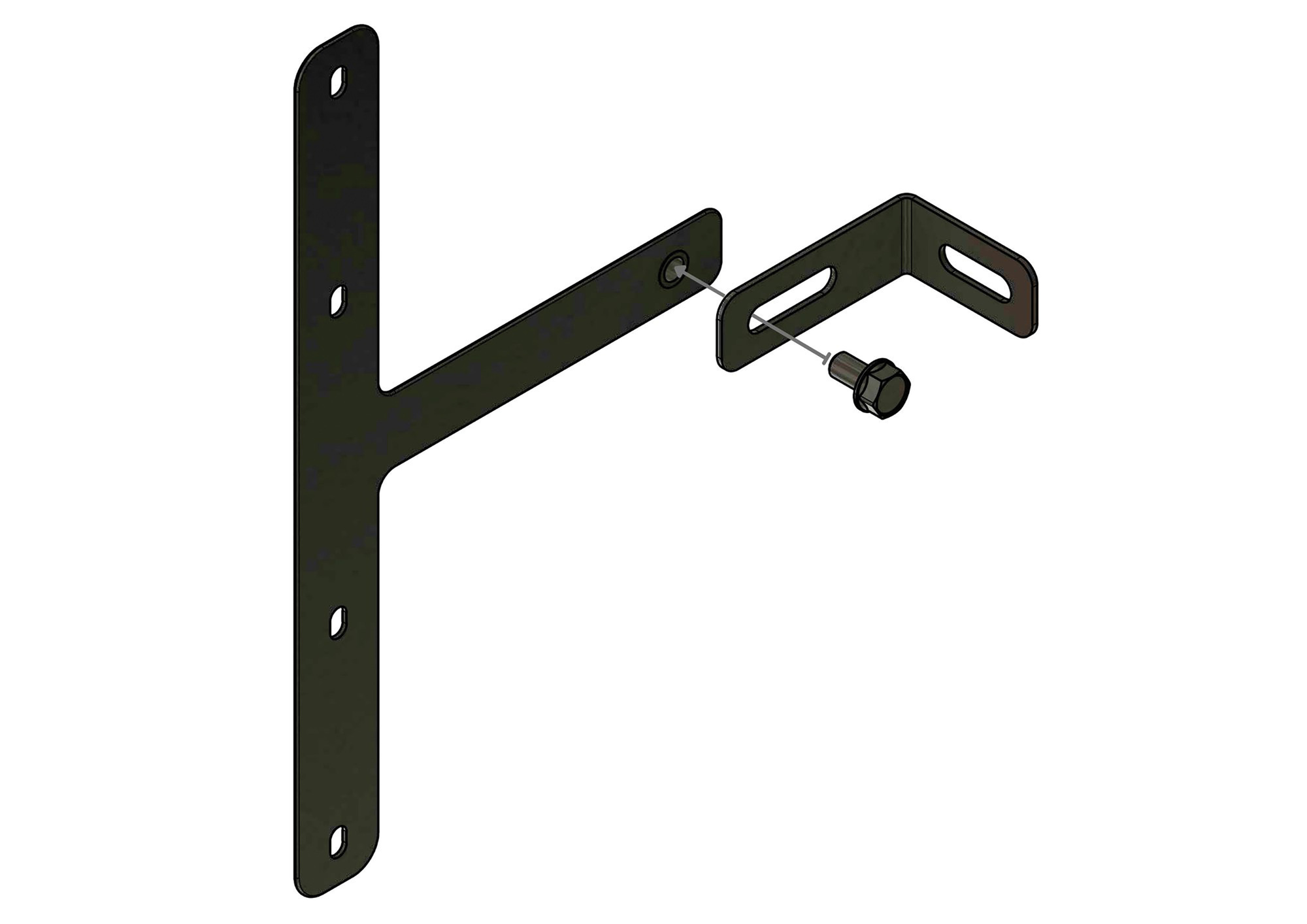
Wall mounting Mounting bracket (Heckert Solar-BMS box part) |
|
4 |
Wall mounting mounting bracket (wall part) |
4 |
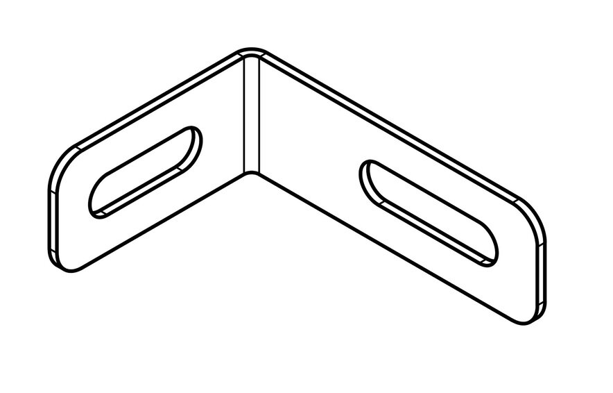
Fixing plates |
|
|
4 |
Screws M4 x 10 |
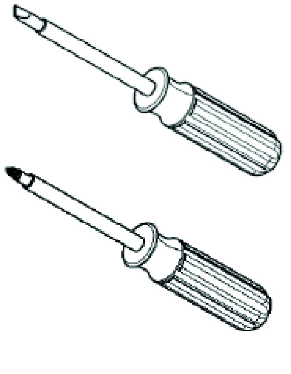
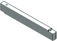
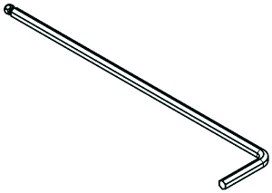
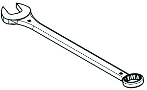
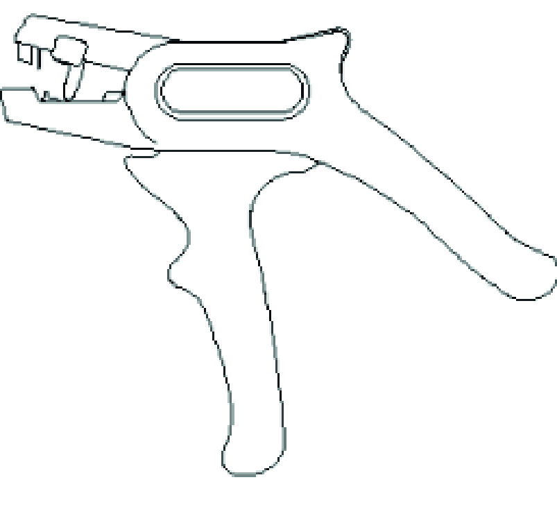
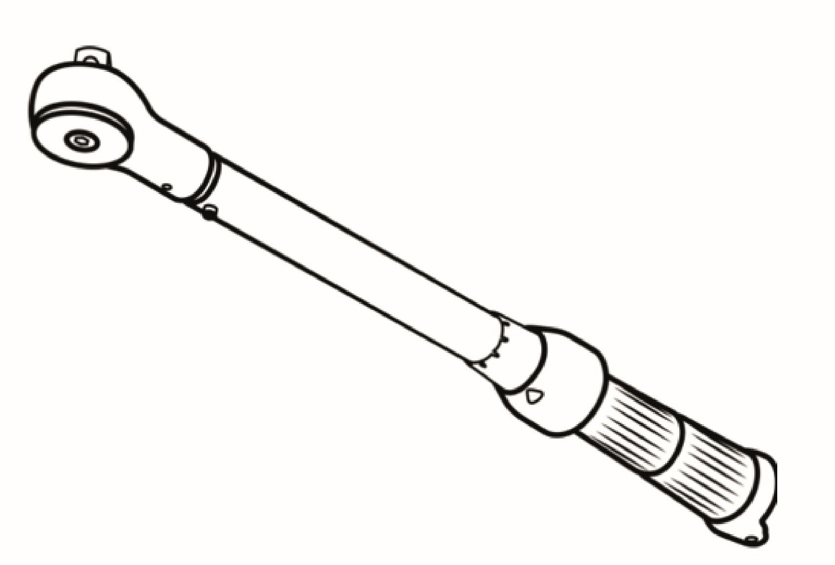
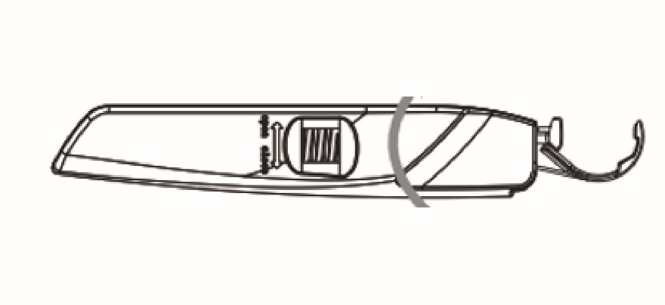
5.2. Tools required
Zur Montage der Komponenten der Anlage wird folgendes Werkzeug benötigt:
| illustration | designation | illustration | designation |
|---|---|---|---|
|
pencil |
|
Spirit level |
|
impact drill or |
|
Screwdriver set |
|
Meter stick |

|
side cutter |
|
Allen key, 3 mm |
|
set of flat spanners |
|
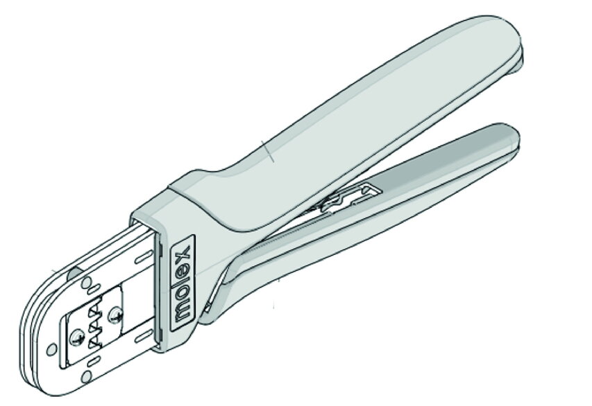
Crimping tool |
|
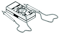
Multimeter |

|
pliers for cable glands |

|
protective eyewear |
|
protective footwear |

|
dust mask |
|
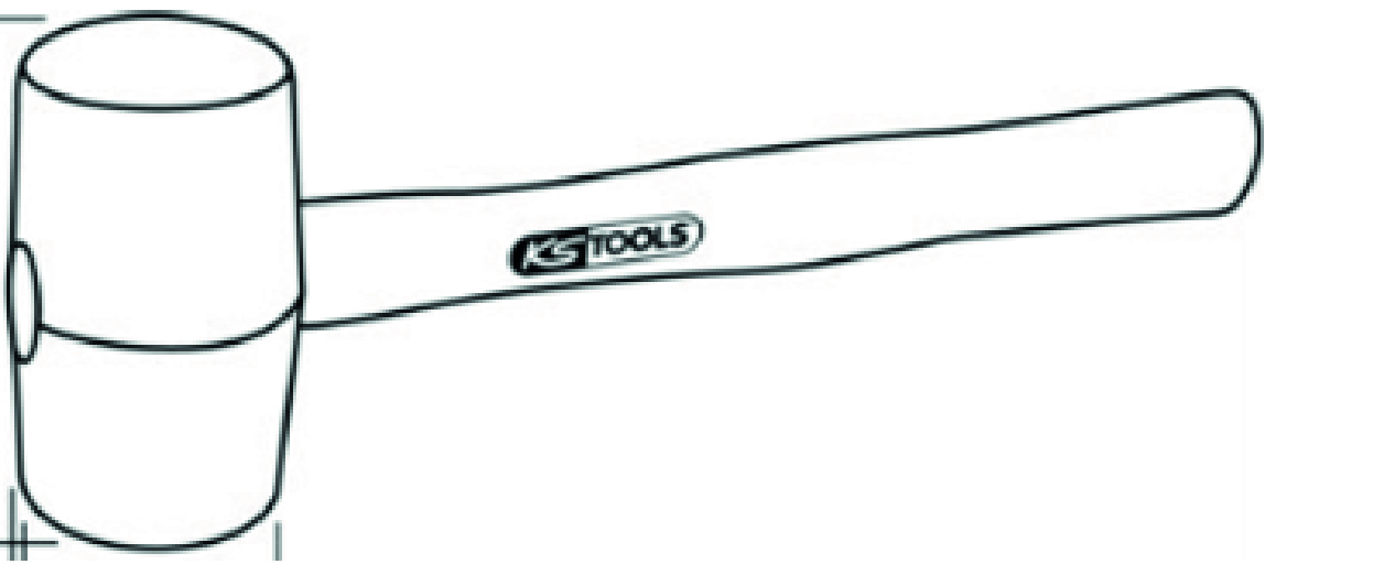
rubber mallet |
|
vacuum cleaner |
|
Wire stripper |

|
Protective gloves |
|
Torque wrench |
|
Insulation stripping knife |
6. Assembly
|
|
|
|
Suitable protective covers must be fitted! |
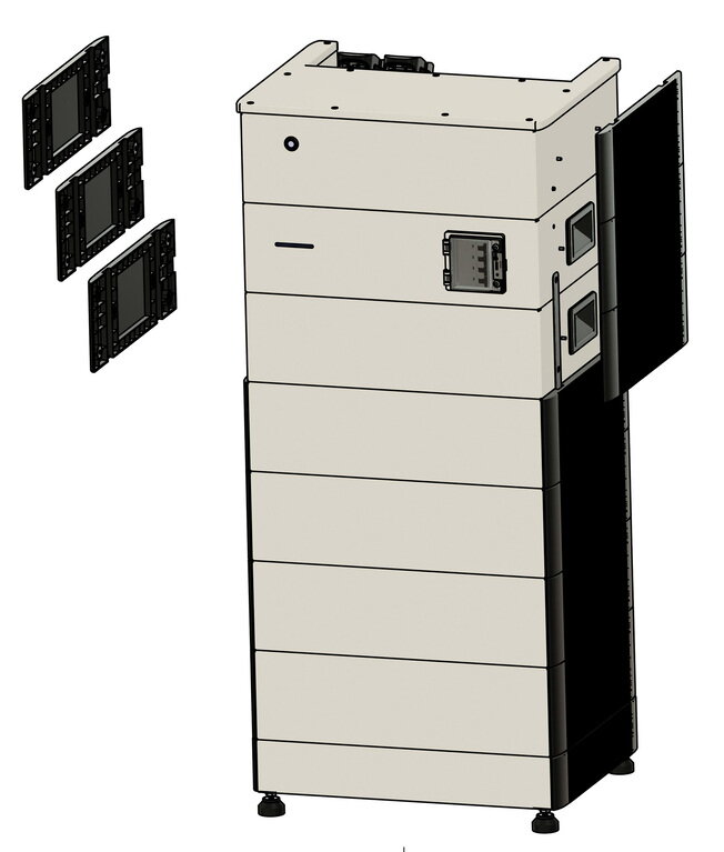
The following components must be installed:
-
Inverter
-
Battery tower with base, battery modules, BMS box and Heckert Solar EMS box
-
Optional:
-
Battery tower with base, battery modules, BMS box and parallel switch box
-
-
Optional:
-
Batterieturm mit Sockel, Batteriemodulen, BMS-Box und Extension-Box
-
Vor der Installation sorgfältig prüfen, ob die Verpackung und die Produkte beschädigt sind und ob alle im Abschnitt [Lieferumfang] aufgeführten Zubehörteile enthalten sind. Wenn ein Teil fehlt oder beschädigt ist, wenden Sie sich an den Hersteller/Händler.
6.1. Montage Wechselrichter
6.1.1. Safety instructions
|
Electric shock from live parts
|
|
Electric shock in the absence of overvoltage protection
|
|
Fire and explosion
|
|
Fire and explosion hazard with deeply discharged battery modules
|
|
Toxic substances, gases and dusts
|
|
Arcing due to short-circuit currents
|
|
Destruction of a measuring device due to overvoltage
|
|
Hot surfaces
|
|
Weight of the inverter
|
|
Sand, dust and moisture |
|
Electrostatic charge
|
|
Cleaning agents
|
6.1.2. Installation conditions and distances at the installation site
Indoor or outdoor installation
We recommend installing the Symphon-E 6, 10 & 15 battery towers in a well-ventilated room without external heat sources. However, the battery tower(s) can also be installed outdoors protected from the weather (e. g. garage).
Installation at and above 2000 m above sea level and in unventilated locations is not permitted.
Also unauthorized installation locations:
-
those with an explosive atmosphere.
-
Places where flammable or oxidizing substances are stored.
-
Wet rooms.
-
places where salty moisture, ammonia, corrosive vapors or acid can ingress into the system.
The storage system should also be inaccessible to children and animals.

-
The inverter must be installed protected from direct sunlight, rain and snow.
-
In conditions outside the optimum temperature range, the performance of the batteries is reduced. (optimum temperature range: +15 °C to +30 °C)
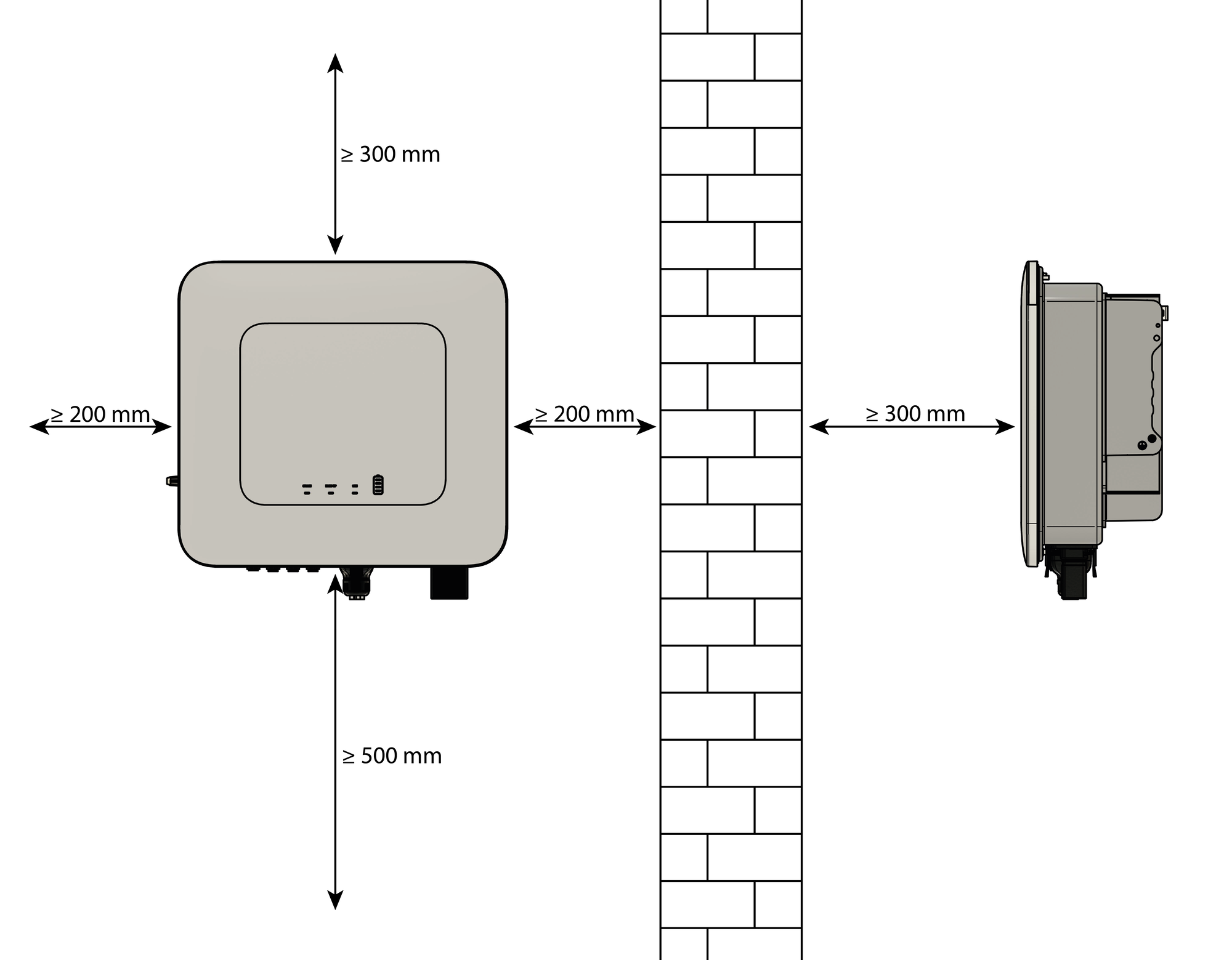
|
Installation conditions
|
6.1.3. Assembly
To install the Symphon-E 6, 10 & 15 inverter on the wall, proceed as follows:
Assembly of the wall bracket
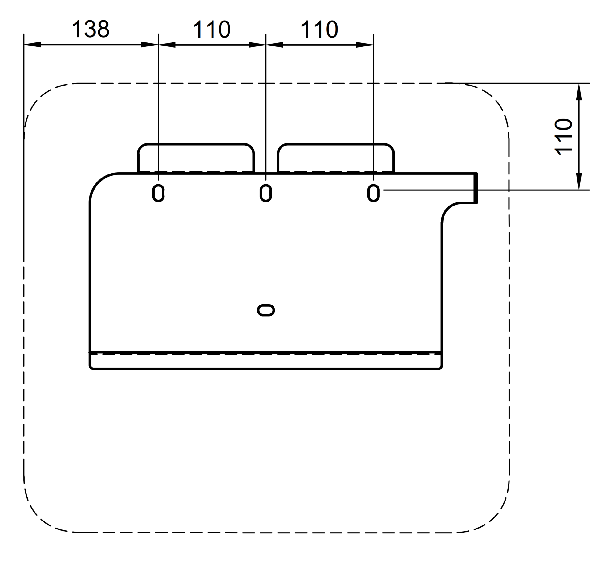
|
Mark and drill holes for wall mount (Ø 8 mm, depth 80 mm) 2. Observe minimum distances. |
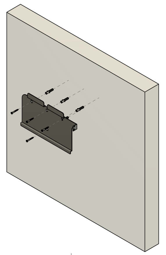
|
3. mount the wall mount on the wall. Always consider the condition of the wall to determine whether the screw anchors can be used. |
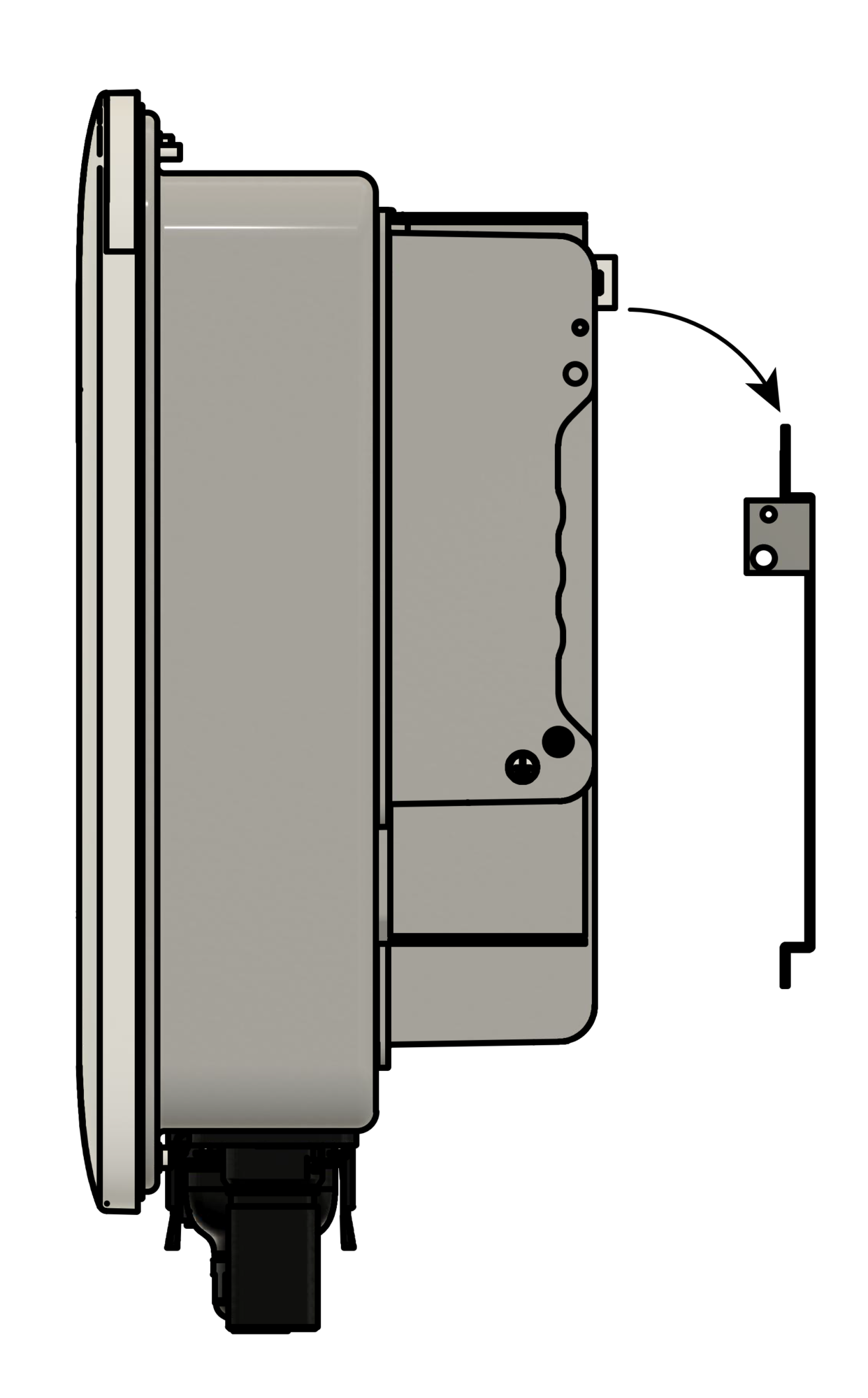
|
Hang the inverter on the top and bottom of the wall mount (remove using the handles). |
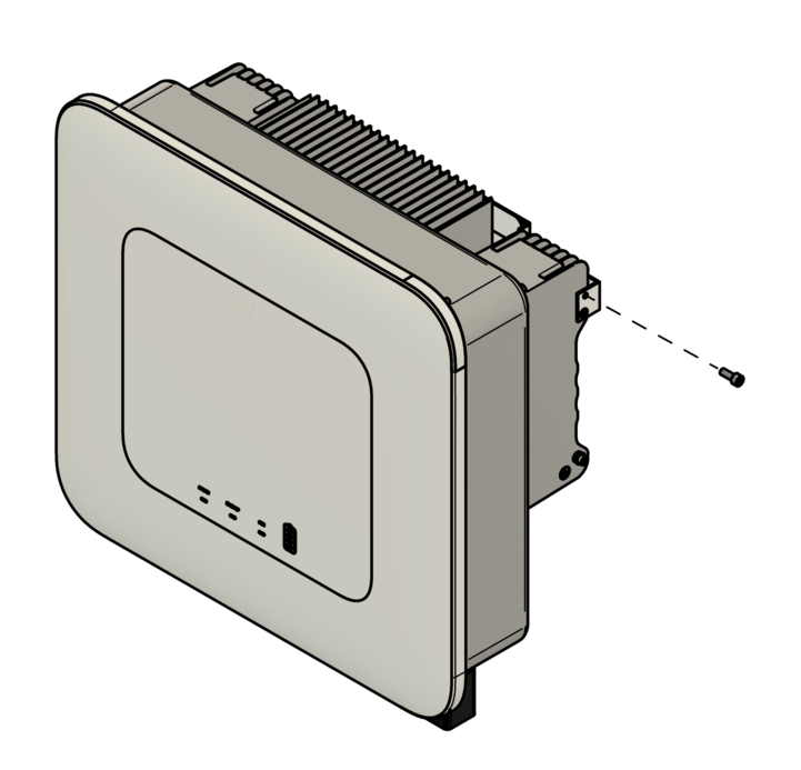
|
Then secure on the right-hand side using the enclosed screw. |
6.2. Montage Batterieturm 1 mit EMS-Box
6.2.1. Safety instructions
|
Electric shock from live parts
|
|
Electric shock in the absence of overvoltage protection
|
|
Fire and explosion
|
|
Fire and explosion if battery modules are deeply discharged
|
|
Toxic substances, gases and dusts
|
|
Arcing due to short-circuit currents
|
|
Destruction of a measuring device due to overvoltage
|
|
Hot surfaces
|
|
Weight of the battery modules
|
|
Sand, dust and moisture
|
|
Electrostatic charging
|
|
Cleaning agents
|
|
Aufstellort
|
|
Installation
|
6.2.2. Conditions at the installation site
Indoor or outdoor installation
We recommend installing the Symphon-E 6, 10 & 15 battery tower indoors. However, the battery tower can also be installed outdoors protected from the weather (e. g. garage).
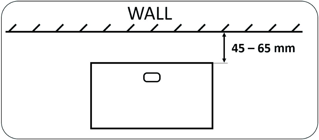
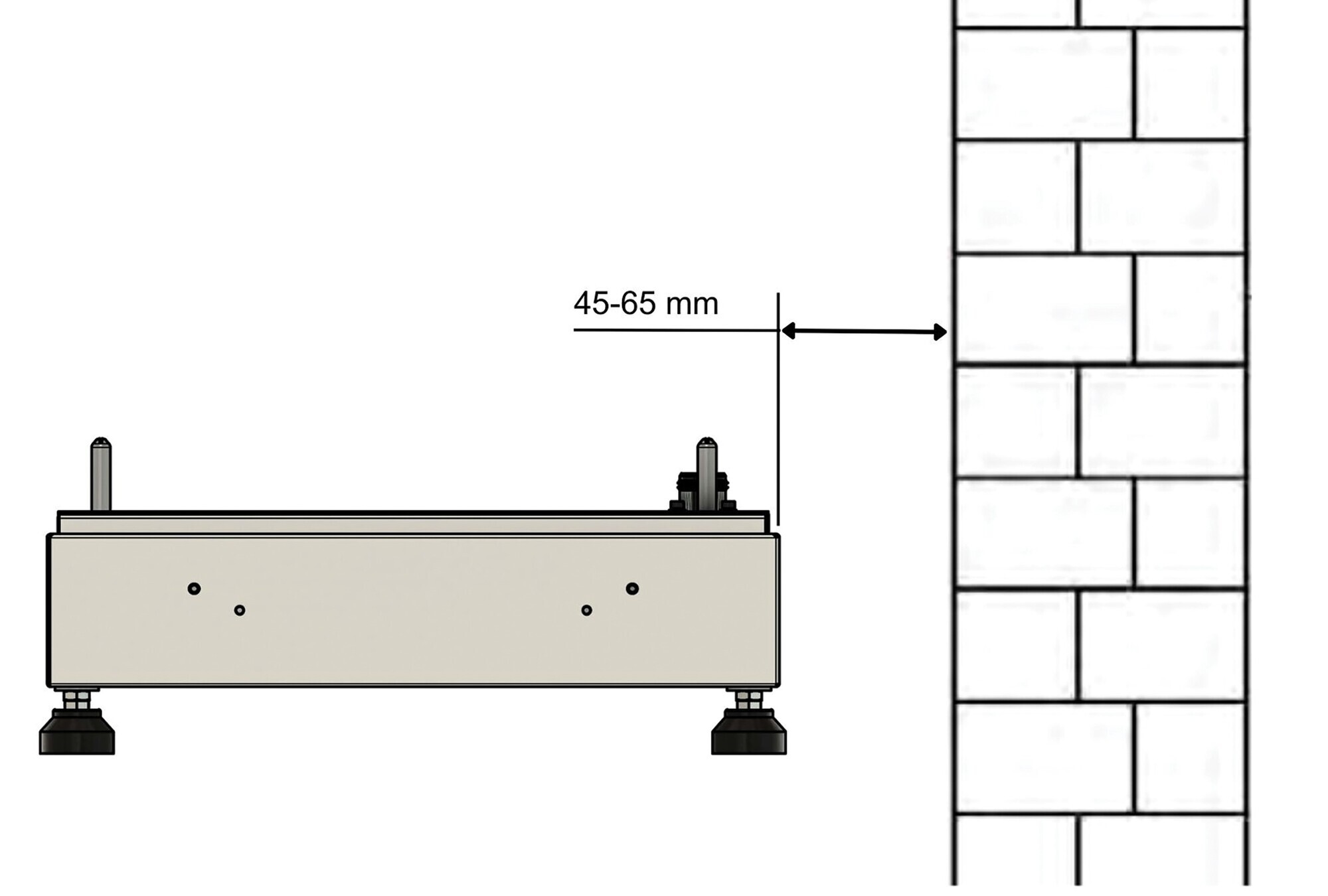
6.2.3. Installation conditions and distances at the installation site
-
The battery tower must be installed protected from direct sunlight, rain and snow.
-
Bei Bedingungen außerhalb des optimalen Temperaturbereich kommt es zur Leistungsreduktion der Batterie. (optimaler Temperaturbereich +15 °C bis +30 °C)
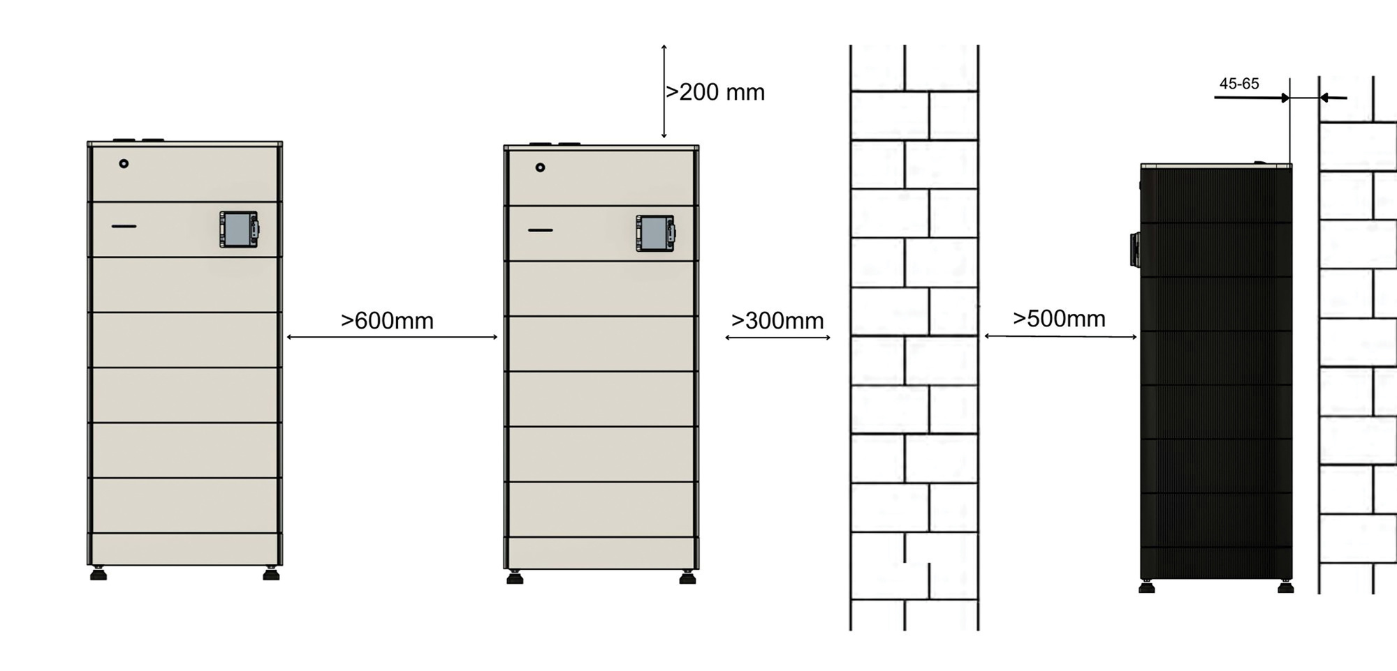
-
A distance of 300 mm from the wall and 600 mm between two battery towers is recommended.
-
A distance of 500 mm from a wall is recommended at the front.
-
The Symphon-E 6, 10 & 15 battery tower and inverter should be installed/mounted on top of each other. If there is not enough space above, the battery tower and inverter can also be installed next to each other.
-
A distance of 200 mm from the ceiling is recommended.
|
If the recommended distances are not observed, installation may be more difficult and derating may occur earlier. |
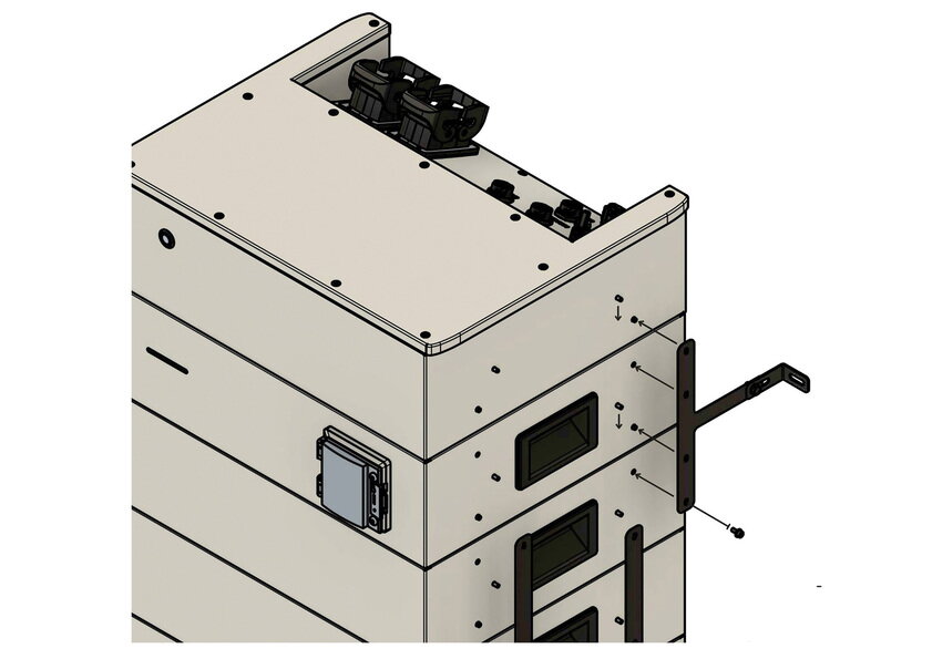
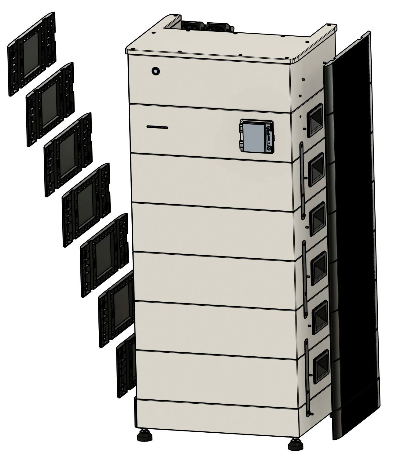
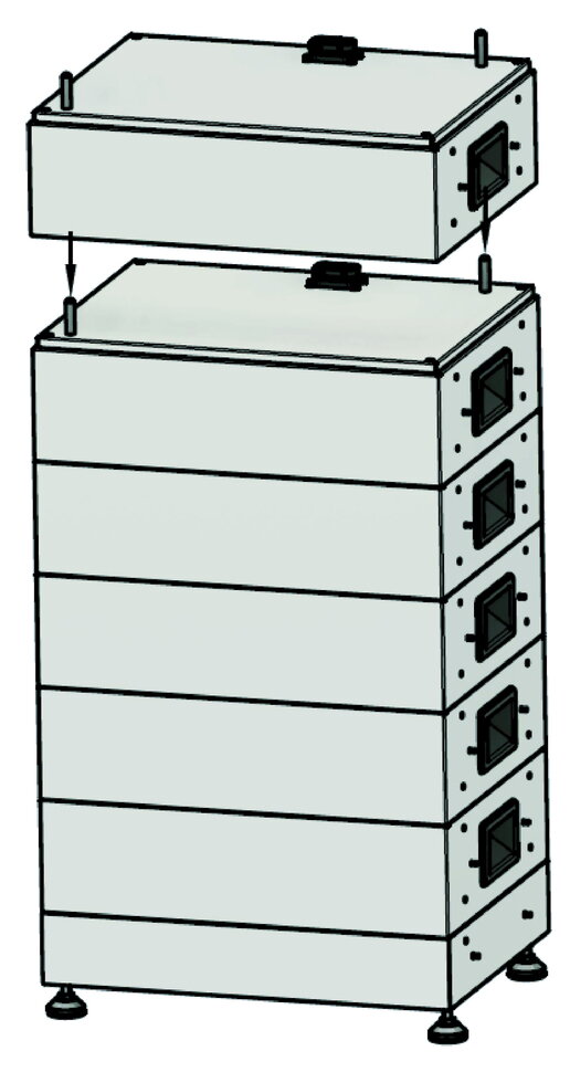
6.2.4. Assembly of battery tower 1 with Heckert Solar EMS box
Proceed as follows to set up the battery tower:
|
|
|
|
|
|
|
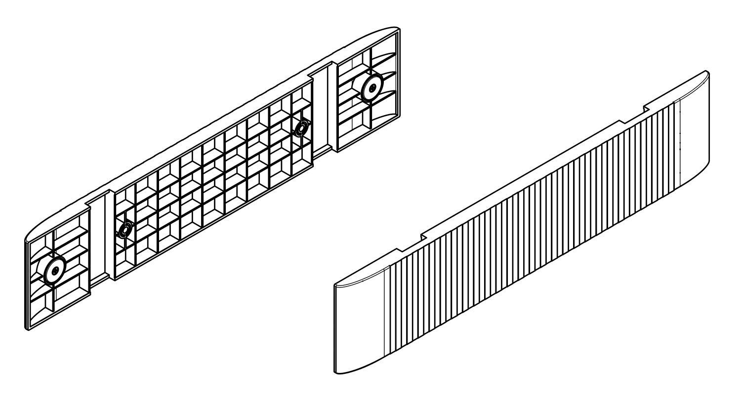
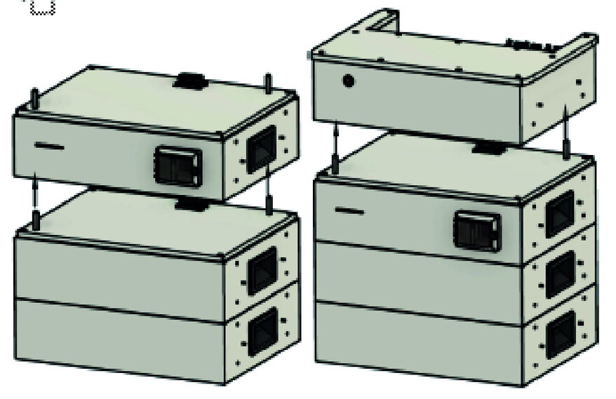
Stack a maximum of 14 Heckert Solar battery modules on one base. |
|
|
|
Electric shock
|
|
|
|
|
|
|
|
|
|
|
|
Sie finden die Aufbauanleitung für 2 oder 3 Batterietürme im Abschnitt [Elektrische Installation weiterer Batterietürme]. |
6.3. Electrical installation
6.3.1. Earthing the inverter and the battery tower
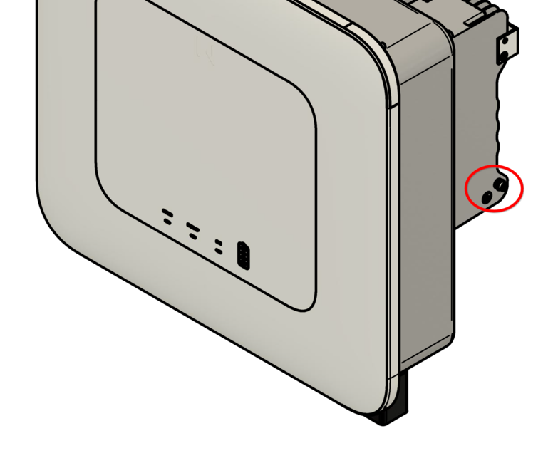
|
|
|
|
|
|
|
The grounding cable requires a cross-section of at least 10 mm2. |
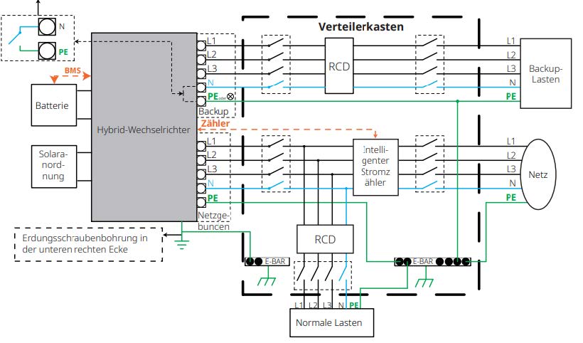
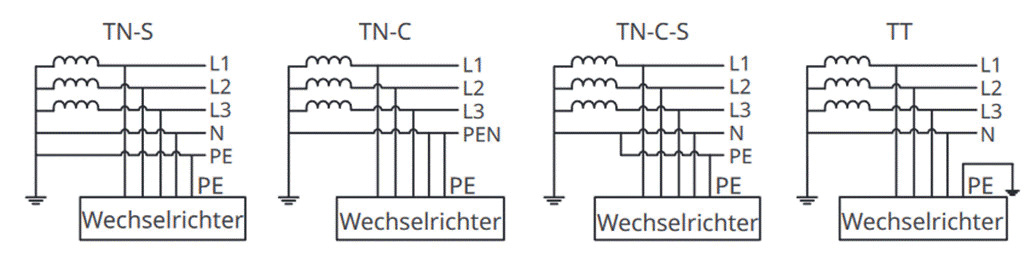
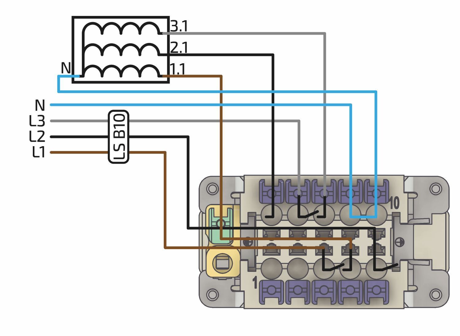
6.4. Approved grid shapes for connecting the Symphon-E 6, 10 & 15
6.4.1. Connection and wiring of the AC circuit
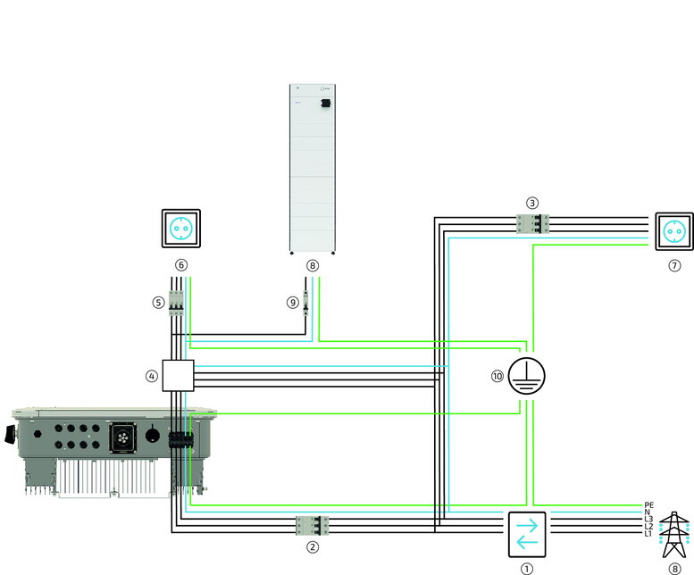
| Pos. | Beschreibung |
|---|---|
1 |
2-Richtungszähler von Energieversorger. |
2 |
Absicherung des Wechselrichters 3-polig (6 kW — 20 A; 10/15 kW — 32 A).* |
3 |
Absicherung der Verbraucher (kein Notstrom) mit RCD Typ A und passenden LS-Schaltern. |
4 |
Serviceschalter zum Umschalten der Notstromlasten auf das Stromnetz (empfohlen). |
5 |
Verbraucher geschützt durch passende LS-Schalter und RCD Typ A 30 mA.** |
6 |
Verbraucher — notstromversorgt maximal 6/10/15 kW — 2 kW/3,333kW/5 kW pro Phase (gilt auch im Normalbetrieb wenn Netz vorhanden!); keine weiteren AC-Erzeuger zulässig |
7 |
Verbraucher nicht notstromversorgt. |
8 |
AC-Versorgung der EMS-Box (falls Verbraucher am Notstromabgang angeschlossen sind). |
9 |
Absicherung maximal C6 oder C10 1-polig. |
10 |
Potentialausgleichsschiene |
* In addition, the currently valid national regulations and the specifications of the relevant grid operator must be observed. (If an RCD is required by the grid operator, an RCD type A with a tripping current of 300 mA is recommended; at 30 mA, unwanted shutdowns may occur).
** Einzuhalten sind die aktuell gültigen nationalen Bestimmungen, die Vorgaben des zugehörigen Netzbetreibers sowie die Vorgaben des Herstellers.
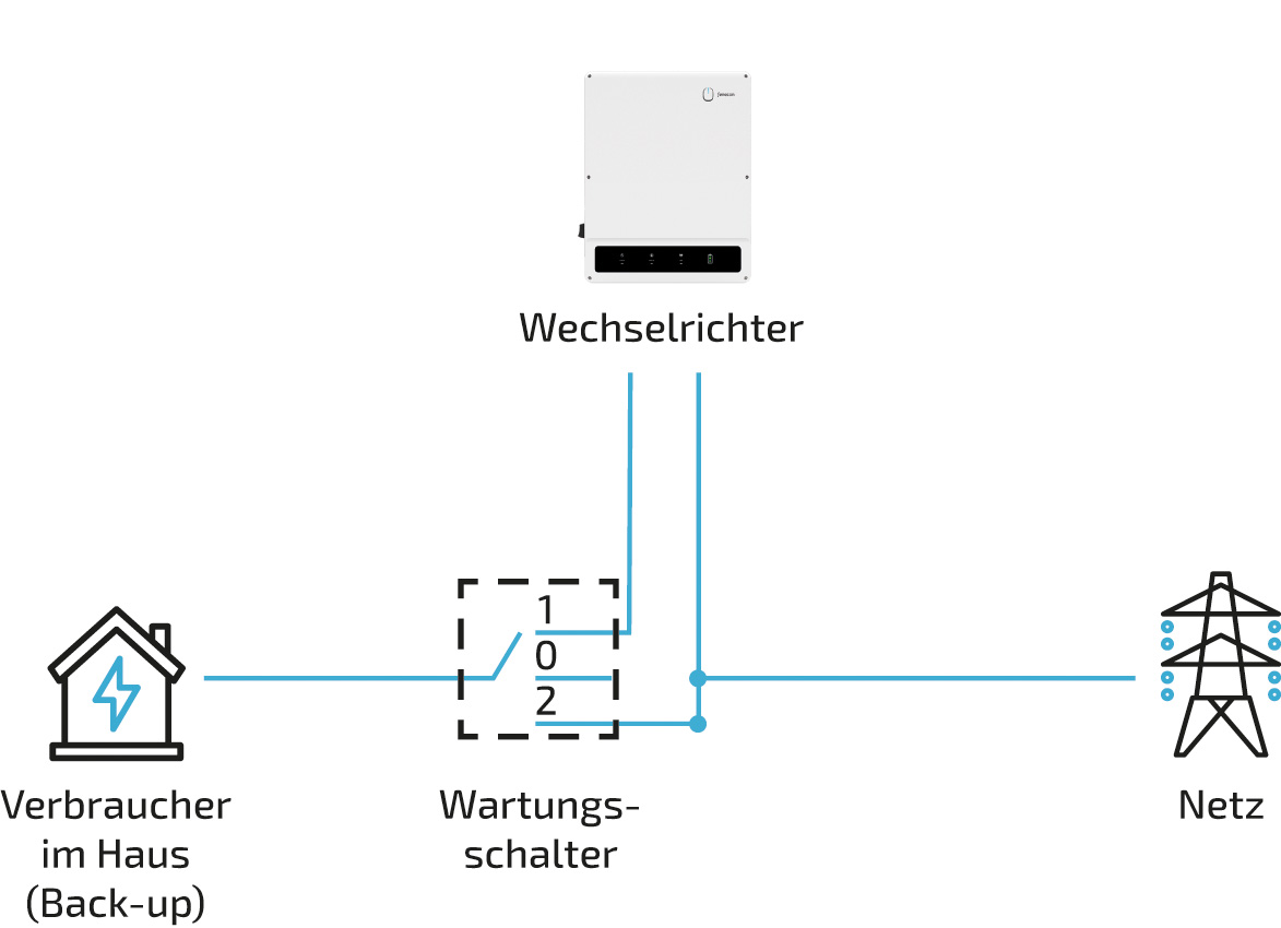
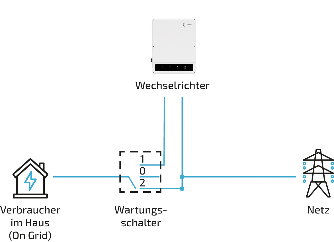
| Pos. | Beschreibung |
|---|---|
1 |
Notstromverbraucher werden über Wechselrichter notstromversorgt (Normalstellung) |
2 |
Notstromverbraucher sind vom Wechselrichter und Netz getrennt |
3 |
Notstromverbraucher werden vom Netz versorgt |
|
The automatic emergency power switchover is not affected by the maintenance switch. |
Item |
Description |
1 |
2 bi-directional meter from energy supplier |
2 |
Fuse protection of the inverter C20/C32 3-pole* |
3 |
Fuse the consumption (no emergency power) with RCD type A and suitable MCBs |
4 |
Consumption, not supplied with emergency power |
5 |
Split-core CT (directly behind grid operator meter) Connection to inverter |
* In addition, the currently valid national regulations and the specifications of the relevant grid operator must be observed. (If an RCD is required by the grid operator, an RCD type A with a tripping current of 300 mA is recommended; at 30 mA, unwanted shutdowns may occur).

|
|
|
|
||
Abschnitt |
Beschreibung |
Maße |
|
1 |
Außendurchmesser |
18 mm |
|
2 |
Länge entmanteltes |
BACKUP: 75 mm |
|
3 |
Länge abisolierter Leiter |
ca. 12 mm2 * |
|
4 |
Querschnitt Leiter |
Home 6: 2,5 mm2 * |
|
|
|
||
|
|
||
|
|
||
Select the cable cross-section, fuse type and fuse value according to the following general conditions: Country-specific installation standards, power class of the device, cable length, type of cable routing, local temperatures
If flexible conductors are involved, wire ferrules must be used accordingly.
|
A 4-pole maintenance switch is recommended. Care must be taken to ensure that no neutral displacement can occur during switching. The correct maintenance switch must be selected by a specialist company, taking into account the conditions on site. |
6.4.2. AC connection of the Heckert Solar EMS box
An external 230-V-power-supply is required to supply the Heckert Solar EMS box.
Dies hat den Zweck, die leere Batterie nicht durch zusätzliche Verbraucher zu belasten. Das kann insbesondere im Winter, wenn keine Sonne scheint, oder wenn Schnee auf der PV-Anlage liegt, vorkommen.
|
|
|
|
|
|
|
|
|
|
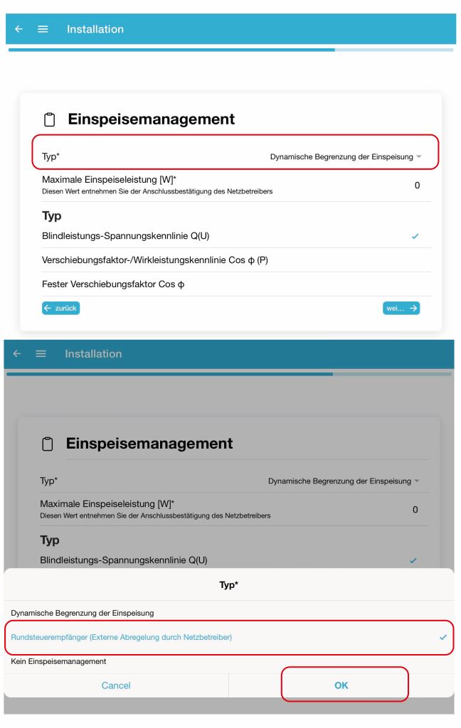
6.5. Erklärung der Funktion "Nulleinspeisung"
Heckert Solar GmbH erklärt hiermit, dass der Wechselrichter:
-
FHI-10-DAH, FHI-10-DAH 16A, FHI-20-DAH, FHI-29,9-DAH
-
FINV-6-2-DAH, FINV-10-2-DAH, FINV-15-2-DAH
in Kombination mit den FHM-120-C-, FHM-C-Energiezählern und der integrierten Messeinrichtung von FINV-6-2-DAH, FINV-10-2-DAH und FINV-15-2-DAH, auf den sich diese Erklärung bezieht, die Nulleinspeisefunktion unterstützt.
Dazu können die Wechselrichter über das Energiemanagement System so konfiguriert werden, dass die erzeugte PV-Energie zu 100 % selbst verwendet wird und nicht in das öffentliche Netz eingespeist wird.
Dazu ist die "Maximale Einspeiseleistung" auf 0 Watt zu setzen.
Folgende Abweichungen sind bei der Nulleinspeisungsfunktion zu beachten:
Heckert Solar WR: ± 50 W pro Phase
Des Weiteren hängt die Genauigkeit vom Leistungsfaktor der Lasten ab. Ein hohes Maß an (Verzerrungs-)Blindleistung wirkt sich negativ auf die Genauigkeit der gemessenen Wirkleistung aus.
Die Erklärung gilt für alle identischen Exemplare des Erzeugnisses. Die Erklärung verliert ihre Gültigkeit, falls an dem Gerät eine Änderung vorgenommen oder dieses unsachgemäß angeschlossen wird, oder nicht nach der Betriebsanleitung aufgebaut wurde, oder der Wechselrichter mit externem Erzeuger betrieben wird.
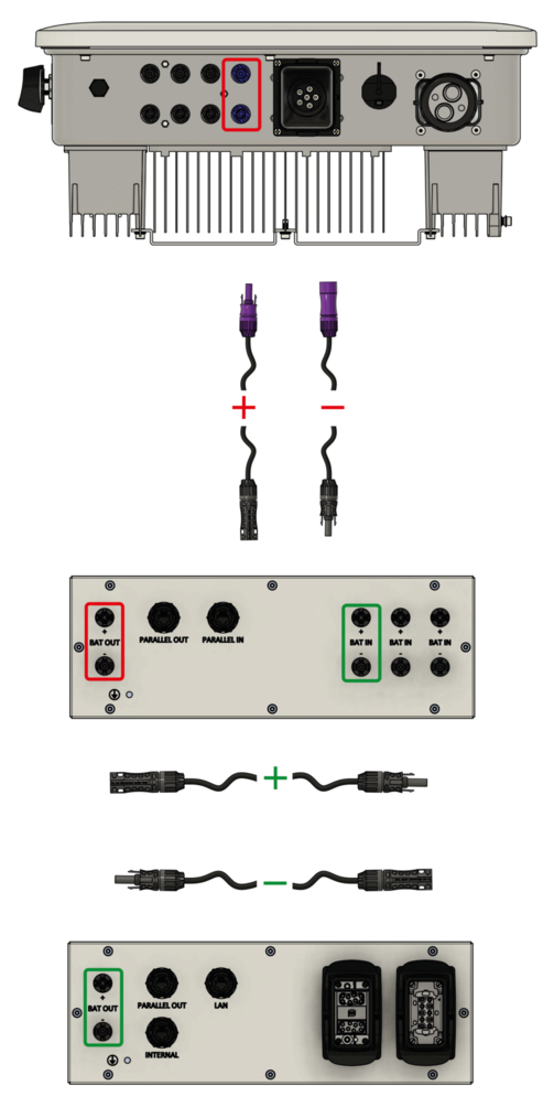
6.5.1. DC-Kabel vom Batterieturm zum Wechselrichter
Bei mehreren Batterietürmen kann dieser Abschnitt übersprungen werden.
|
Sie finden die Aufbauanleitung für 2 oder 3 Batterietürme im Abschnitt [Elektrische Installation weiterer Batterietürme]. |
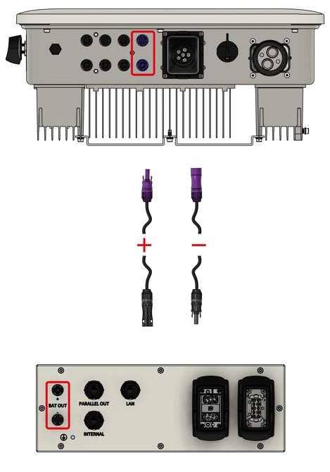
|
|
|
The DC plugs used on the battery side are not compatible with commercially available MC4 plugs. |
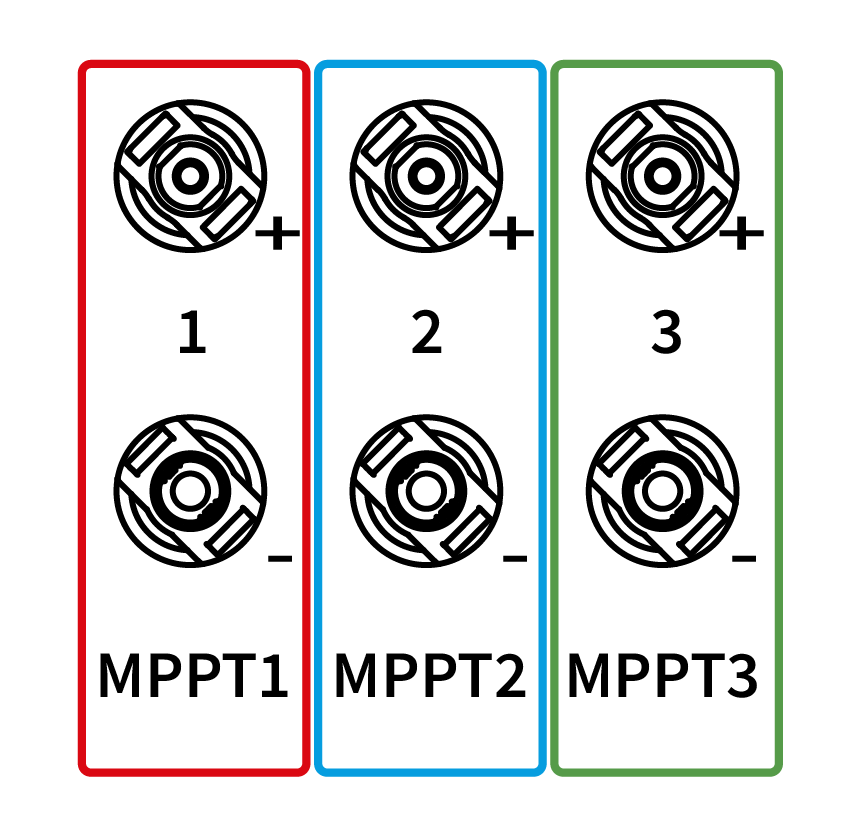
6.5.2. Connection and cabling of PV system
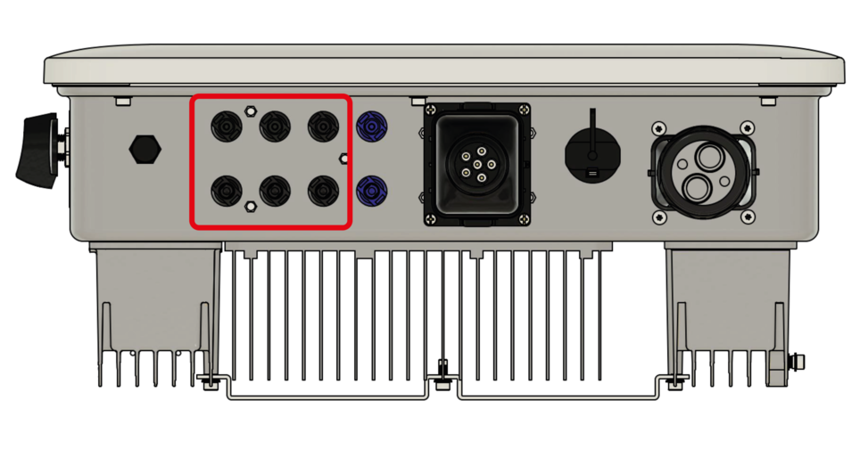
|
The various PV strings can be connected directly to the PV inputs on the inverter. The 6 kW variant has 2 MPPTs, each with one input (red; blue). For the 10 kW and 15 kW variants, 3 MPPTs are available, each with one input (red; blue; green) |
|
|
Type 2 overvoltage protection is integrated in the inverter. |
6.5.3. Communication between inverter and EMS box
|
|
|
Variante A
|
|
Variante B
|
|
|
|
|
|
|
|
|
|
|
Wenn ansteuerbare Verbraucher installiert und eine der nachfolgenden EMS-Erweiterungen gekauft wurden, können die nachfolgenden beiden Schritte vorerst vernachlässigt werden.
|
|
|
|
|
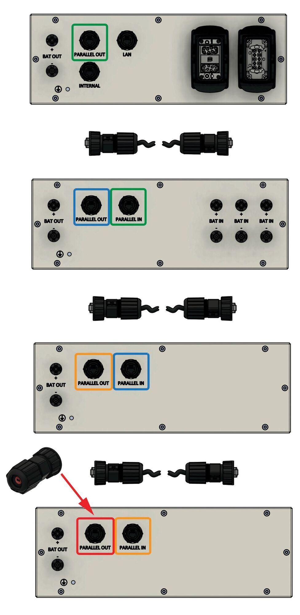
6.5.4. Communication from a battery tower

|
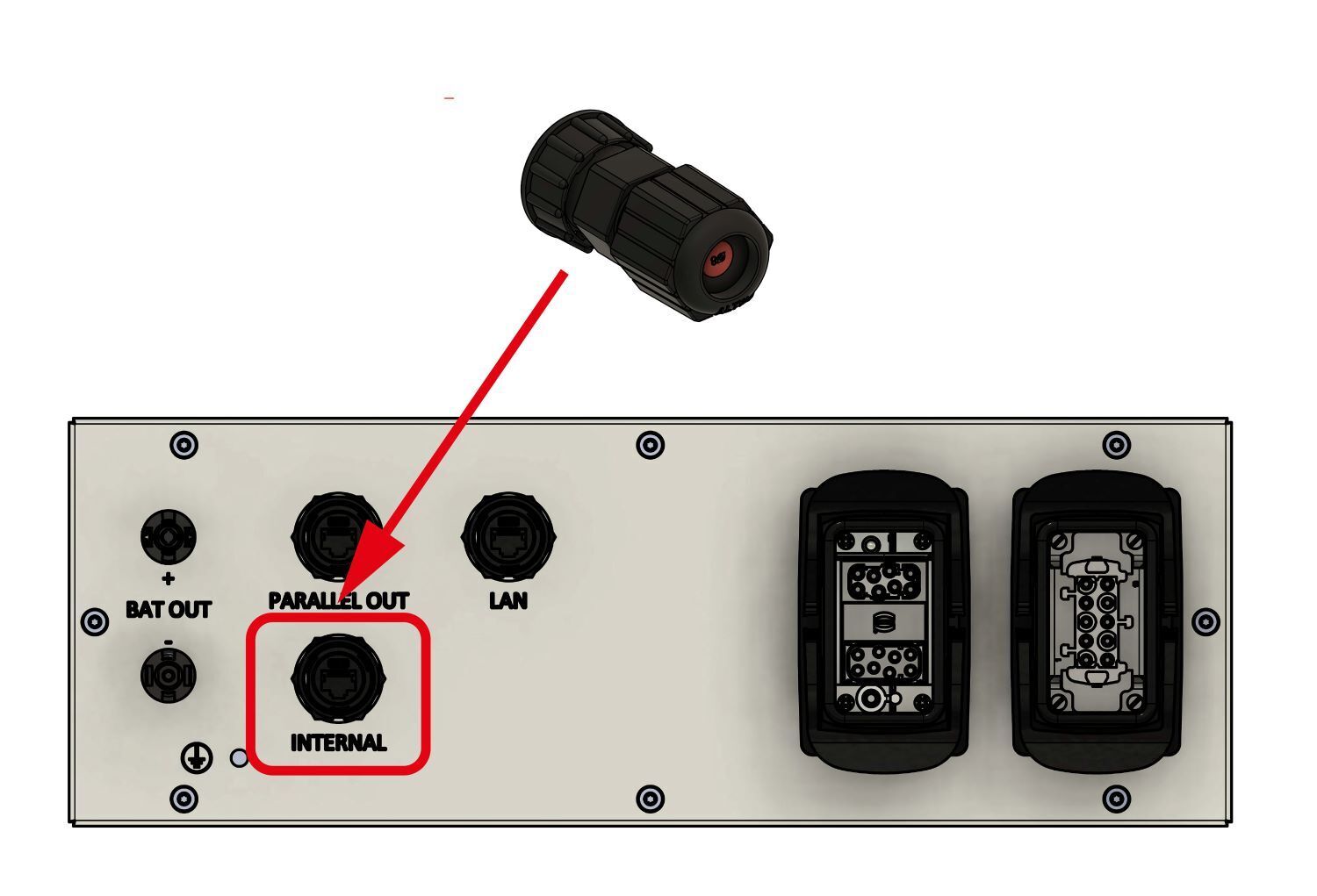
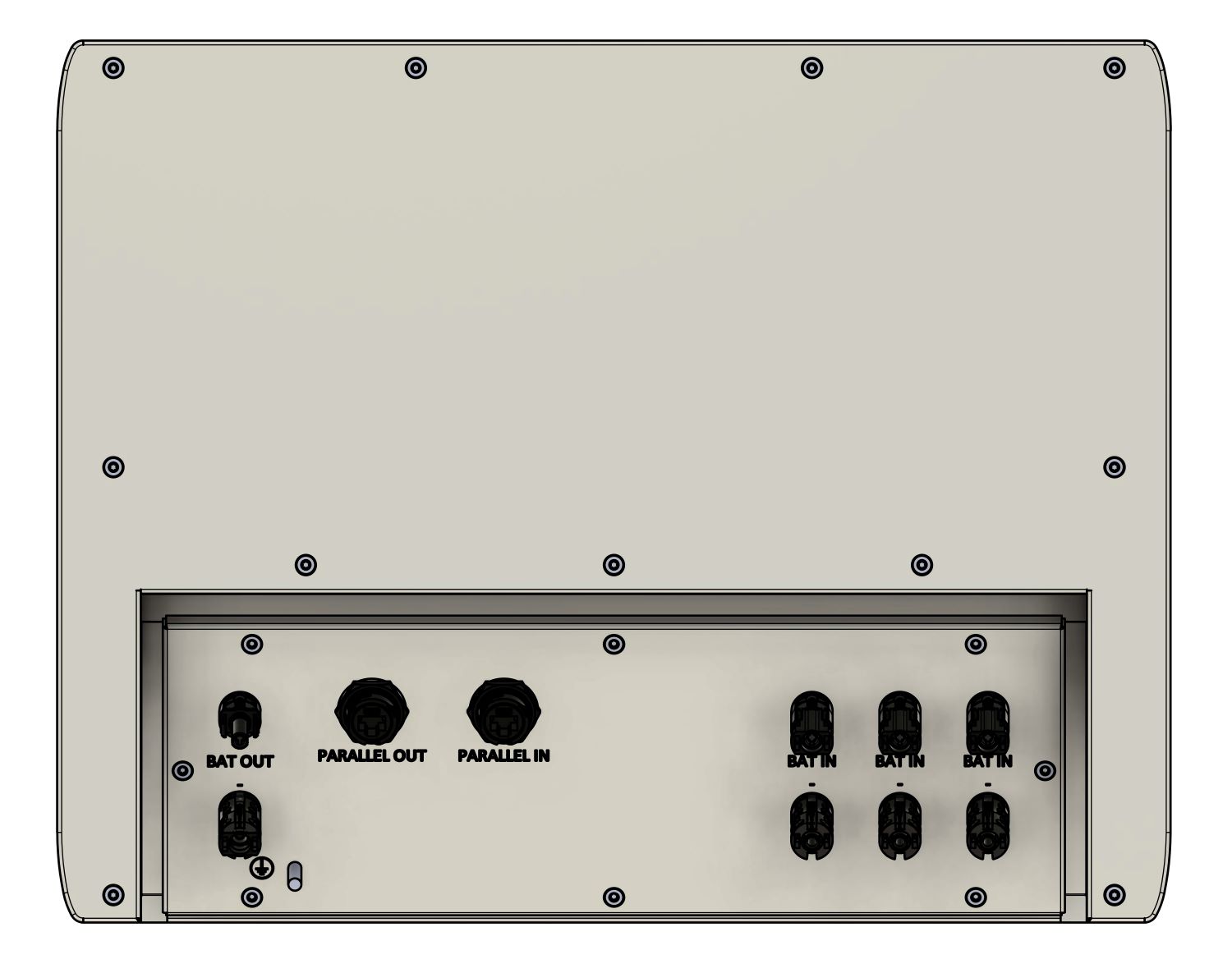
If only one battery tower is installed, the jumper plug (included) must be plugged into the PARALLEL OUT connection and locked by turning the underside. |
|
Sie finden die Aufbauanleitung für 2 oder 3 Batterietürme im Abschnitt [Elektrische Installation weiterer Batterietürme]. |
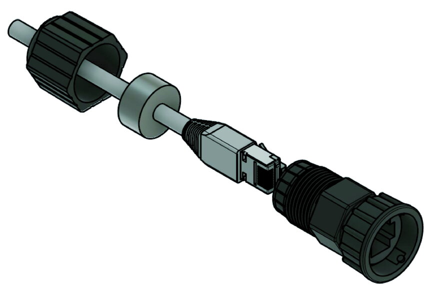
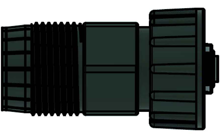
6.5.5. Communication with the customer network
|
|
|
If the battery tower is installed indoors, this point can be skipped and the network cable can be connected directly. |
|
|
|
|
|
The electrical energy storage system does not offer WiFi functionality. |
6.6. Connection and wiring of the system’s measuring device
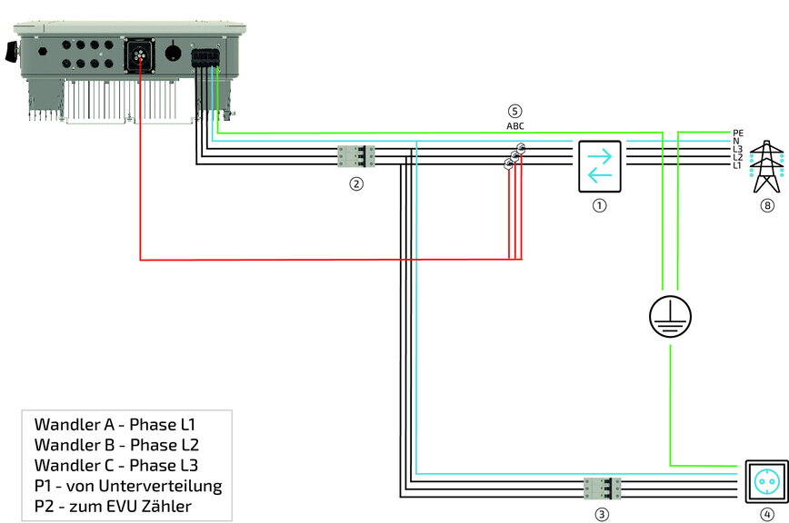
6.6.1. Standard split-core CT
Three split-core CTs with a 10 m long cable are included with the system as standard. No additional measuring device needs to be installed in the meter cabinet. The required voltage data is measured directly at the inverter.
| Item | Description |
|---|---|
1 |
Bi-directional meter from energy supplier |
2 |
Inverter fuse protection C20/C32 3-pole* |
3 |
Loads fuse (no emergency power) with RCD type A and suitable MCBs |
4 |
Load(s) (not supplied with emergency power) |
5 |
Split-core CT (directly behind utility meter), connection to inverter |
|
In addition, the currently valid national regulations and the specifications of the relevant grid operator must be observed. (If an RCD is required by the grid operator, an RCD type A with a tripping current of 300 mA is recommended; at 30 mA, unwanted shutdowns may occur). |
6.6.2. Connection — Split-core CT variant A
|
|
|
|
|
|
|
|
6.6.3. Connection — Split-core CT variant B
|
For variant B, a network cable (min. CAT5e) of the appropriate length is required. |
|
|
|
|
|
|
|
|
|
|
|
Die maximale Strombelastbarkeit liegt bei 120 A pro Phase. |
6.6.4. Optional split-core CTs with external measuring device
If the cable (10 m) of the standard split-core CTs is too short, an external measuring device with already connected split-core CTs can be installed as an option. A maximum cable length of 100 m is possible between the measuring device and the inverter.
| Item | Description |
|---|---|
1 |
Bi-directional meter from energy supplier |
2 |
Inverter fuse protection C20/C32 3-pole* |
3 |
Loads fuse (no emergency power) with RCD type A and suitable MCBs |
4 |
Load(s) (not supplied with emergency power) |
5 |
Split-core CT (directly behind grid operator meter), connection to inverter |
6 |
Energy Meter |
7 |
Fuse for the Energy Meter (recommended) B6 3-pole |
|
In addition, the currently valid national regulations and the specifications of the relevant grid operator must be observed. (If an RCD is required by the grid operator, an RCD type A with a tripping current of 300 mA is recommended; at 30 mA, unwanted shutdowns may occur). |
|
|
|
|
|
|
Für den folgenden Schritt kann ein Standard-CAT6-Netzwerkkabel oder -Verlegekabel mit aufgecrimptem Stecker verwendet werden.
|
|
|
|
Variante A
|
|
Variante B
|
|
|
|
Die maximale Strombelastbarkeit liegt bei 120 A pro Phase. |
6.6.5. Abdeckung des Internal-Eingangs (optional)
|
Optionally, a network connector housing with filler plug (included in the scope of delivery) can be used as a cover for the internal connection. |
|
An IP classification is only guaranteed if the corresponding plugs are locked at all connections. |
7. Parallel connection of several battery towers
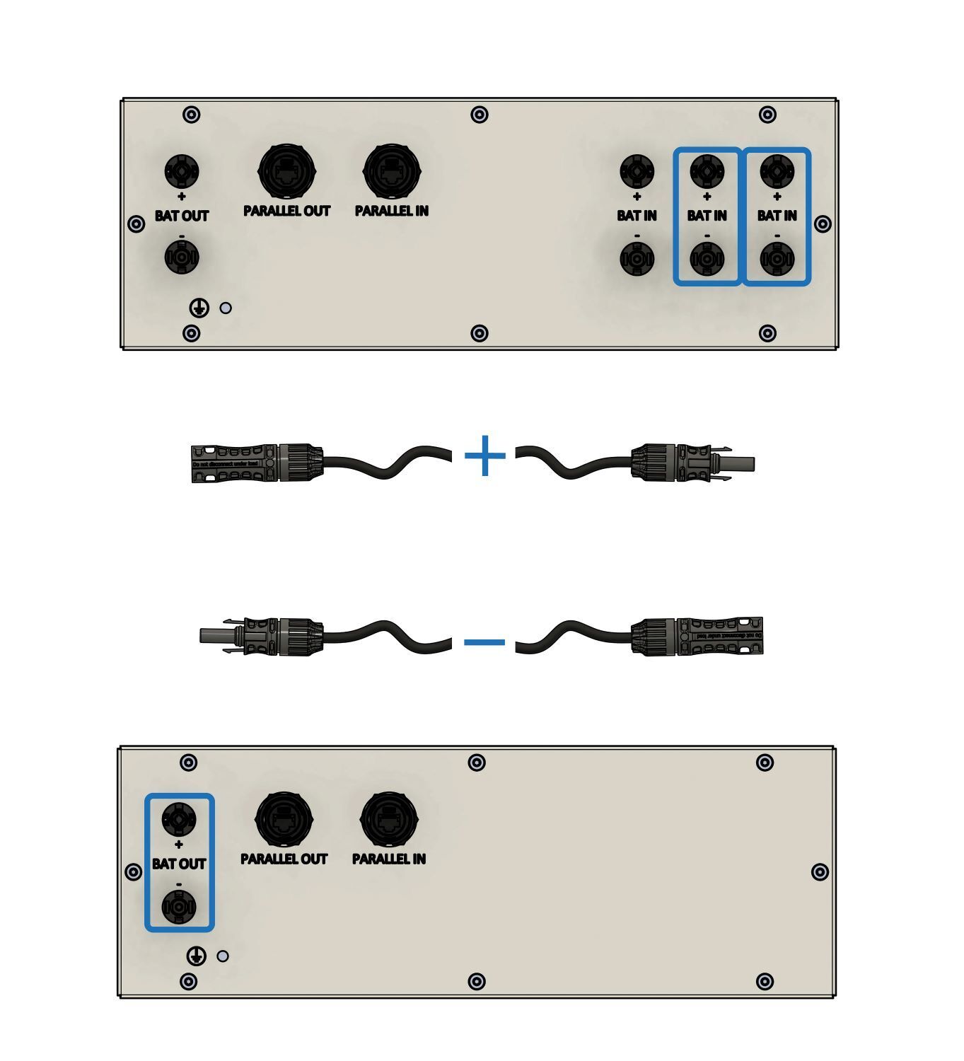
7.1. Assembly of further battery towers
7.1.1. Assembly of battery tower 2 with Heckert Solar parallel switch box
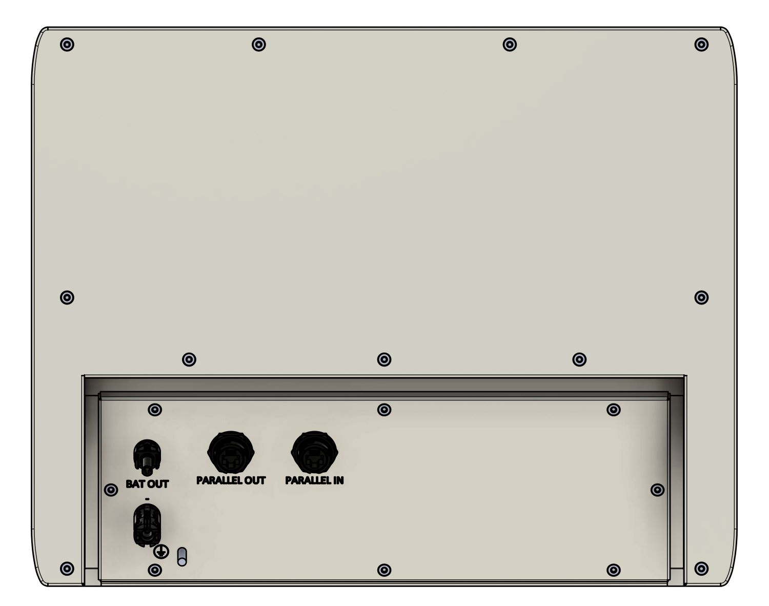
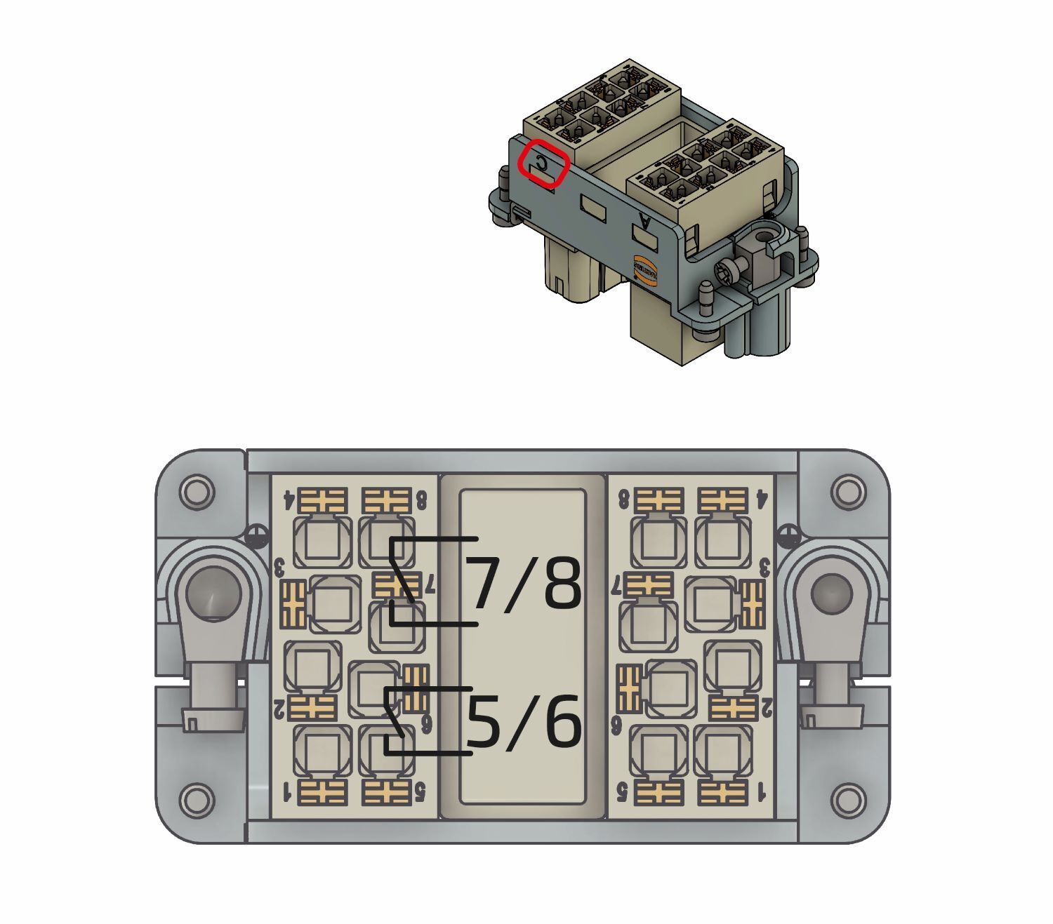
If a second battery tower is available, the parallel switch box is plugged onto the second battery tower instead of the EMS box.
|
Hierfür wiederholen Sie die Schritte aus dem Abschnitt [Montage Batterieturm 1 mit Heckert Solar-EMS-Box]. Bei Schritt 8 stecken Sie anstatt der Heckert Solar-EMS-Box die Heckert Solar-Parallelschaltbox auf. |
7.1.2. Assembly of battery tower(s) 3 to 4 with Heckert Solar Extension box
Wenn ein dritter bis vierter Batterieturm vorhanden ist, wird auf den dritten bis vierten Batterieturm statt der EMS-Box eine Extension-Box aufgesteckt.
|
Hierfür wiederholen Sie die Schritte aus dem Abschnitt [Montage Batterieturm 1 mit Heckert Solar-EMS-Box]. Bei Schritt 8 stecken Sie anstatt der Heckert Solar-EMS-Box die Heckert Solar-Extension-Box auf. |
7.2. Electrical installation of additional battery towers
7.2.1. DC-Kabel zwischen zwei Batterietürmen und dem Wechselrichter
|
|
7.2.2. DC cable between the third to fourth battery tower and parallel switch box
|
|
7.3. Communication of further battery towers
7.3.1. Communication between two to four battery towers
|
|
8. Initial commissioning
8.1. Checking the installation, connections and cabling
Check the system as follows before initial commissioning:
-
All components (distances, environment, mounting) are installed correctly.
-
All internal wiring is complete and properly connected.
-
All external supply lines (power supply, communication cable) are properly connected.
-
All connected loads are matched to the system and the necessary settings have been made.
-
All necessary tests of the system were carried out in accordance with the standards.
|
Commissioning may only be carried out by trained specialist personnel. |
|
|
This is indicated in the installation and service instructions:
|
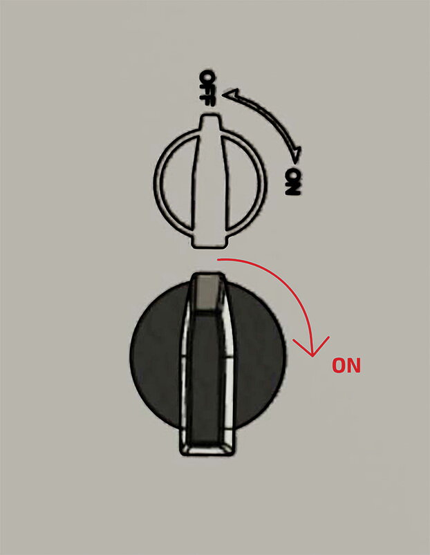
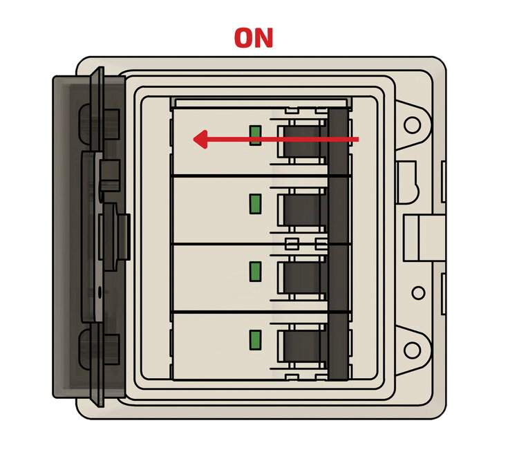
8.2. Switching the system on/off
8.2.1. Switch on
|
|
|
|

|
|
|
The system is restarted by pressing the push-button on the front of the EMS box. Restarting the system can take up to three minutes. |
|
If the system has not yet been configured, the battery goes into error mode or switches off. The inverter only starts after configuration and only then synchronizes to the grid. |
8.2.2. Switch off

|
|
|
|
|
|
8.3. Configuration via commissioning wizard
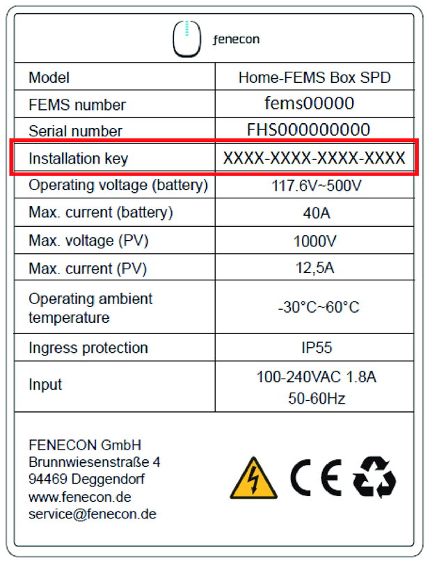
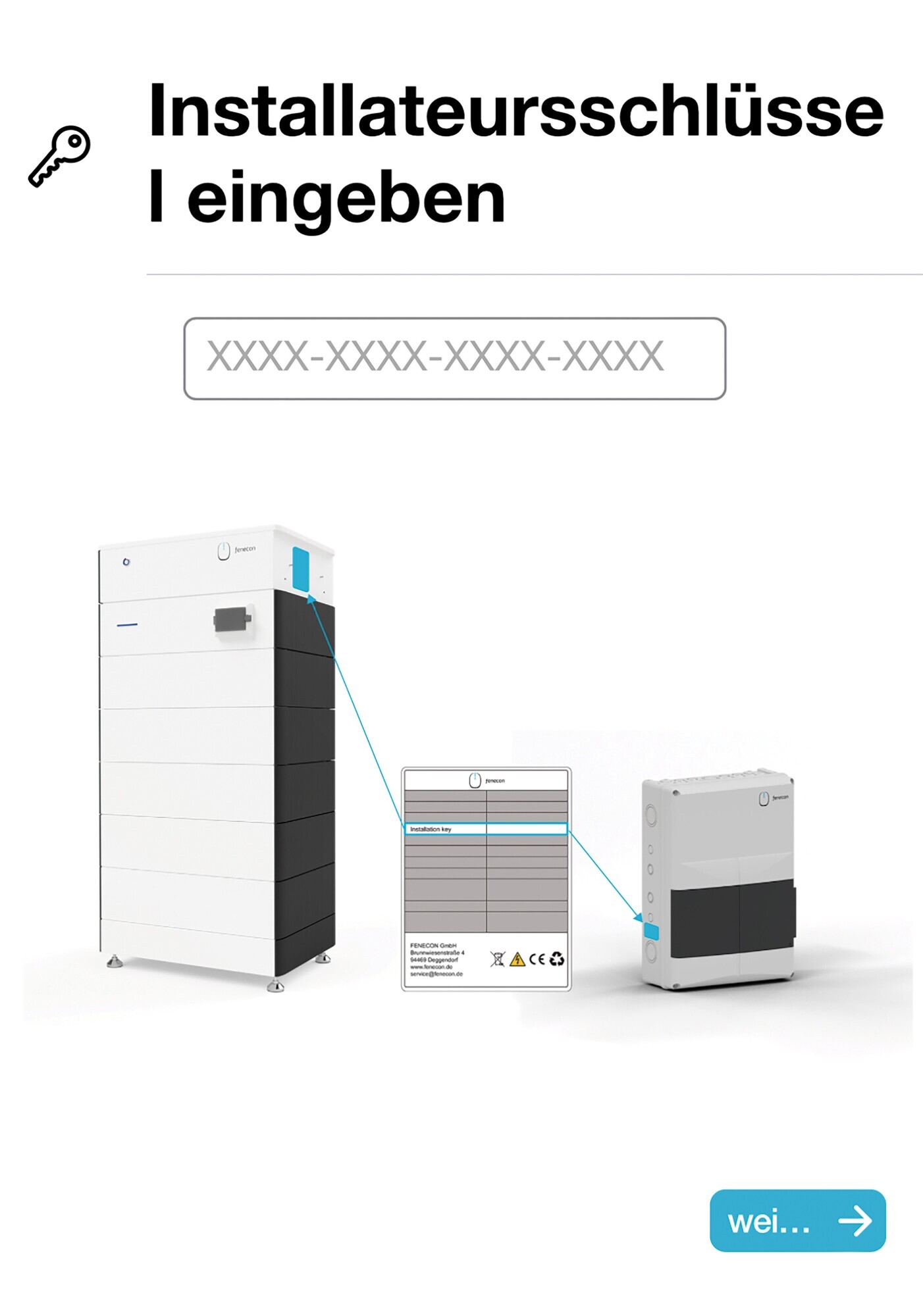
Open the Heckert Solar homepage and click on the login for EMS Online Monitoring "EMS login" in the top right-hand corner. Alternatively, you can use the following QR code or link to access the page.

|
|

|
|
|
|
|
|
|
|
|
|
|
|
|
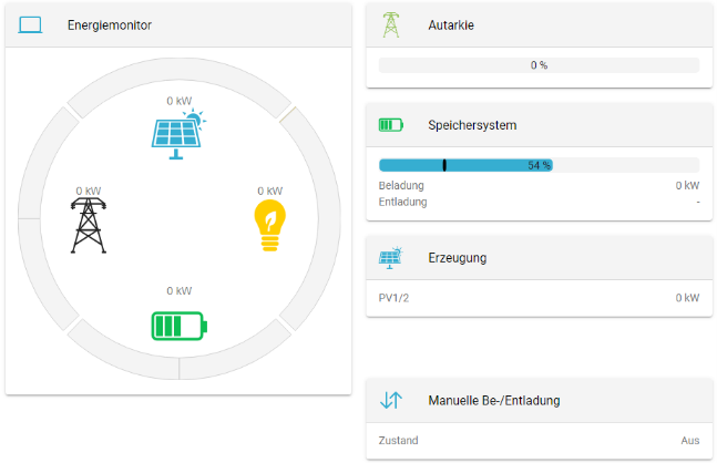
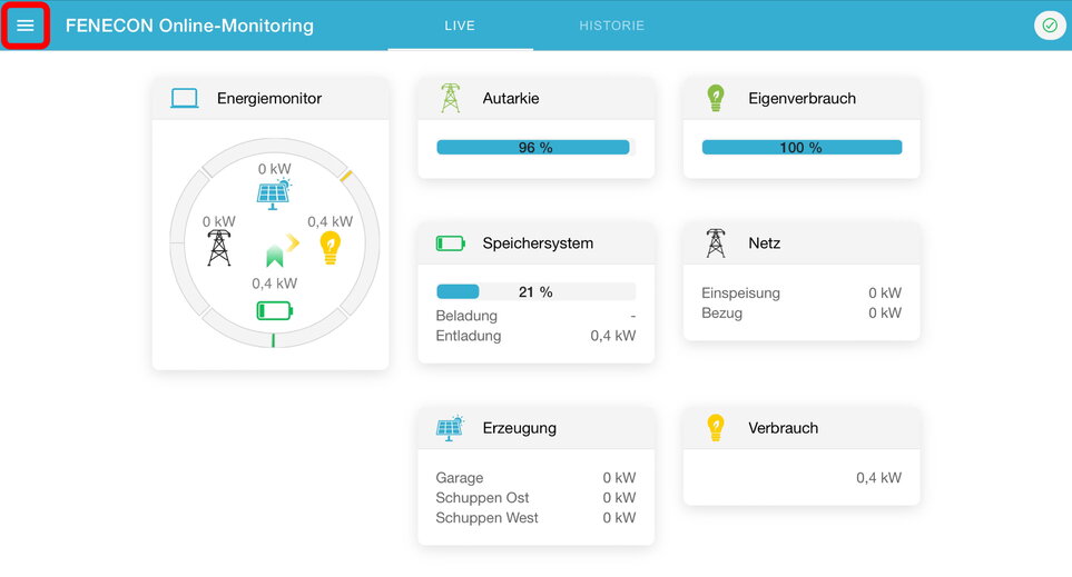
9. EMS-Online-Monitoring
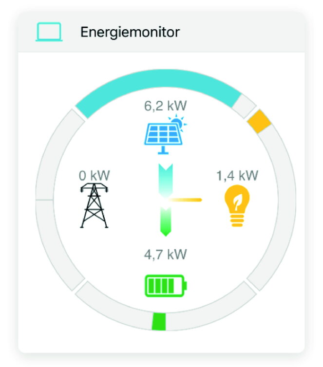
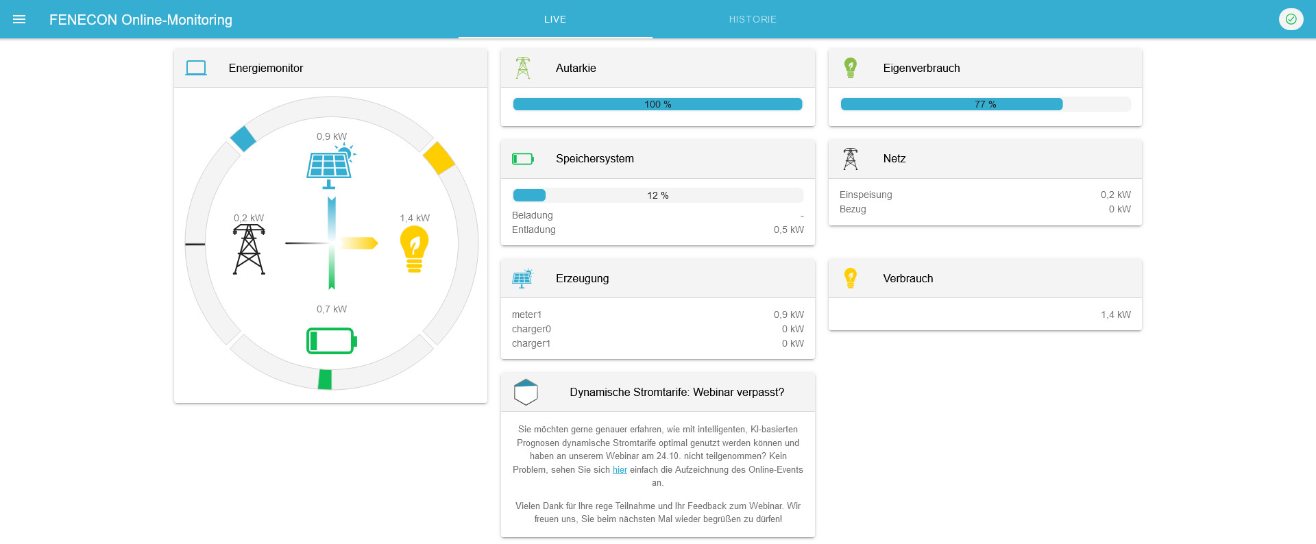
The EMS Online Monitoring is used to visualize all energy flows in your system. The energy monitor shows live data on grid consumption or grid feed-in, PV production, charging/discharging of the battery storage system and electricity consumption. Other widgets display the percentage of self-sufficiency and self-consumption. In addition, the individual widgets offer a detailed view, which can also be used to view the performance values with phase accuracy.
In addition to the pure information display, all EMS extensions purchased additionally , such as those for integrating a heat pump, Heating element, e-charging station or combined heat and power plant (CHP), are also listed in the Online Monitoring. Their functionality can be controlled via the corresponding widget.
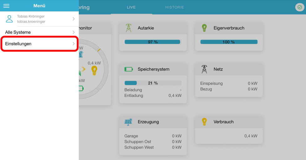
Zusätzlich zur Live-Ansicht bietet die Historie die Möglichkeit, selbstgewählte Zeiträume für das Online-Monitoring auszuwählen. Über das Info-Symbol kann der Status des Gesamtsystems als auch der einzelnen Komponenten zu jedem Zeitpunkt überwacht werden.
9.1. Access data
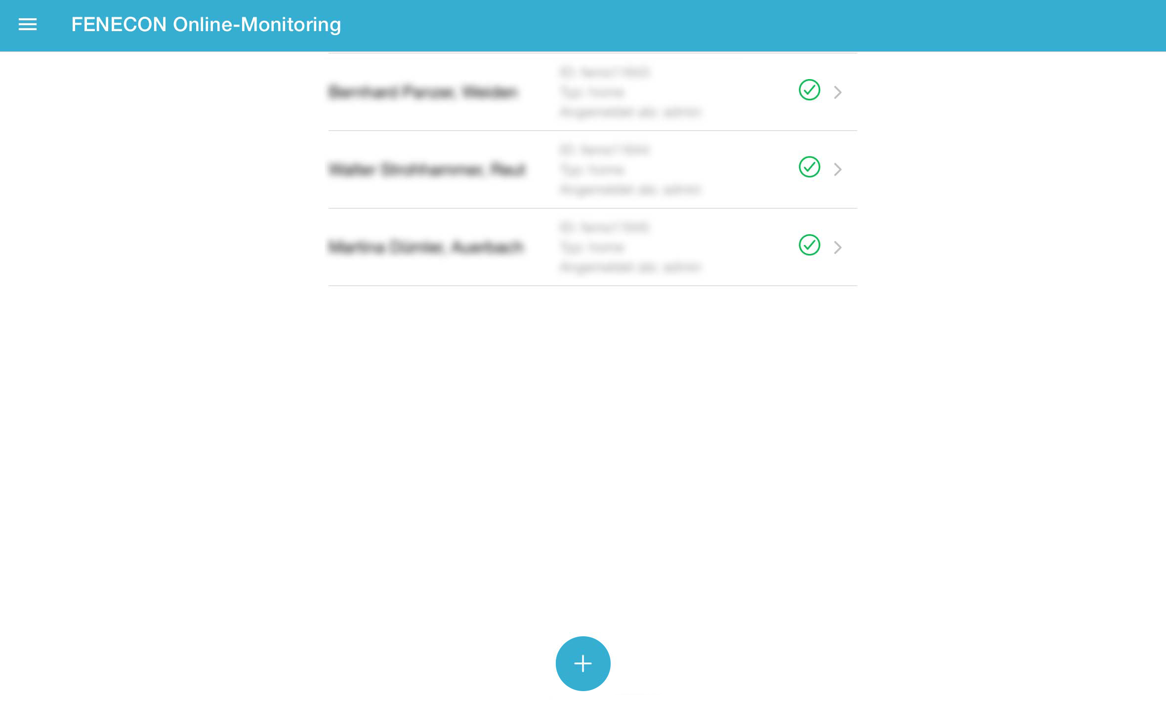
Der Zugang zum EMS-Online-Monitoring ist nach Endkunden und Installateur getrennt.
9.1.1. Access for the end customer
Access for the end customer is generated automatically once commissioning is complete and sent to the end customer by email.
The terms and conditions still need to be confirmed here, then the monitoring is available without restrictions.
Sollten zusätzliche Benutzer auf die Anlage zugreifen wollen, so müssen diese einen eigenen Benutzeraccount erstellen. Dies erfolgt wie im Abschnitt Konfiguration per Inbetriebnahme-Assistent beschrieben, hier muss jedoch in der Kopfzeile "BENUTZER" ausgewählt werden.
Nach erfolgreicher Erstellung eines zusätzlichen Benutzeraccounts benötigen wir lediglich eine Mail an service@fenecon.de, mit der genutzten Mailadresse und der betroffenen EMS-Nummer, die Verknüpfung erfolgt durch uns und somit können weitere Benutzter das Online-Monitoring einer Anlage nutzen.
9.1.2. Access for the installer
Der Installateurs-Zugang kann wie im Abschnitt Konfiguration per Inbetriebnahme-Assistent beschrieben auf der Heckert Solar-Homepage erstellt werden. Der Zugang ist für die erfolgreiche Inbetriebnahme erforderlich.
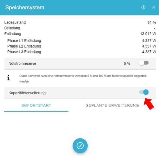
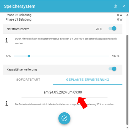
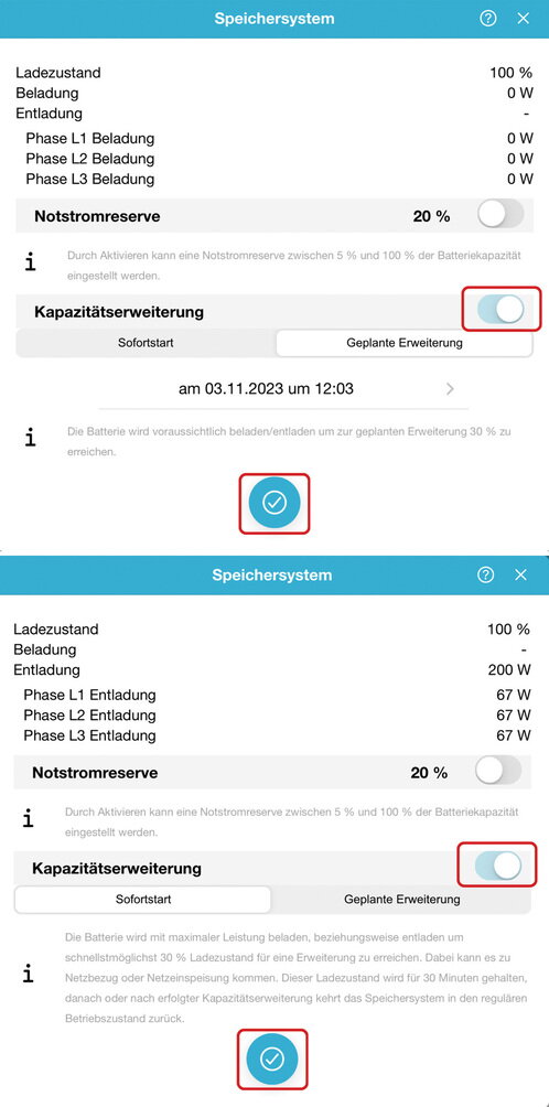
10. Capacity expansion of the system
The capacity can also be extended at a later date, there is no time limit.
Es wird mit zusätzlichen neuen Batteriemodulen nicht die maximale Kapazität erreicht, da sich neue Module den alten Modulen angleichen.
10.1. Capacity expansion of the battery tower
by one or more battery modules
Der Batterieturm kann auf bis zu 14 Batteriemodule in einem Batterieturm erweitert werden.
If the electrical energy storage system is expanded with additional battery modules after commissioning, proceed as follows:
|
After a capacity expansion, the commissioning protocol must be carried out again. |
|
|
|
|
|
|
|
|
|
|
|
|
The capacity can also be extended at a later date; there is no time limit here. You will not reach the full capacity with the new battery module, as the new module adapts to the old modules.
If the battery tower is extended by additional battery modules after several weeks or months, the following procedure must be followed:
29-30 % SoC |
|
|
|
|
|
|
|
|
|
|
|
|
|
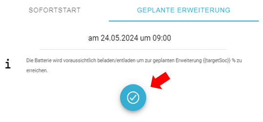
11. Kapazitätserweiterung des Systems
um einen oder mehrere Batterietürme
Die Kapazität des Systems kann nachträglich durch einen oder mehrere Batterietürme mit der gleichen Kapazität erweitert werden. Hier gibt es keine zeitliche Begrenzung.
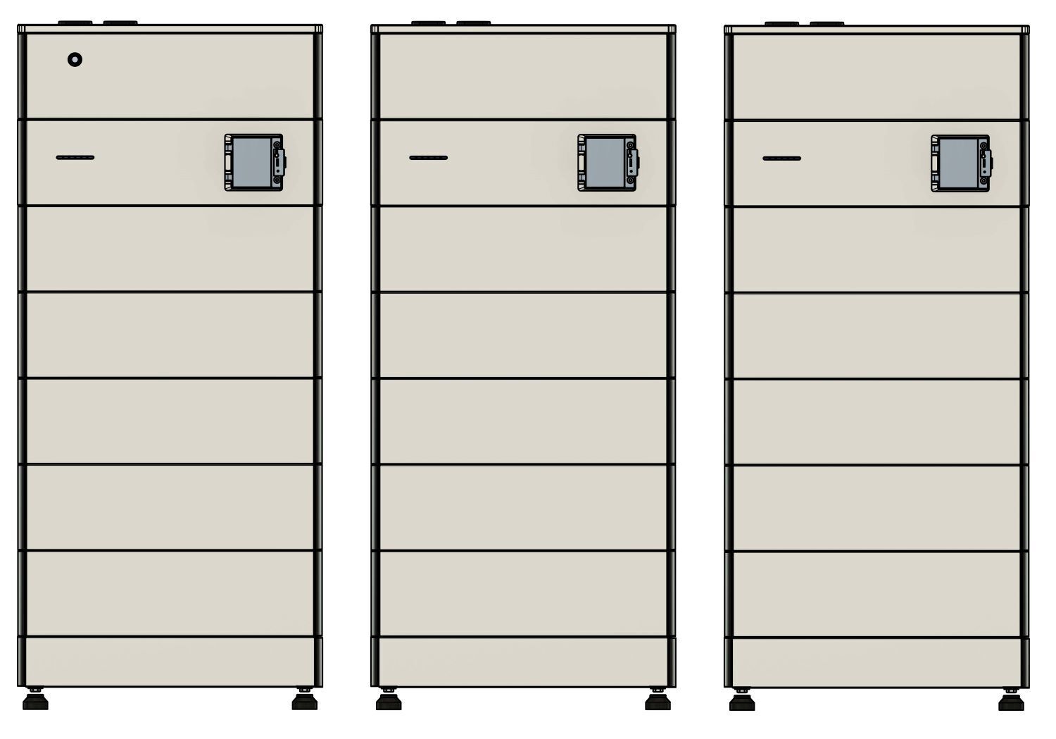
Der Maximalausbau des Symphon-E 6, 10 & 15-Systems umfasst bis zu 4 Batterietürme mit je 3 bis 14 Batteriemodulen und maximal 156,8 kWh.
The full capacity of new battery modules cannot be fully reached as they will adapt to the old modules.
Vor der Erweiterung muss wie folgt vorgegangen werden:
|
|
|
|
|
|
|
|
|
|
12. EMS extensions
The integrated relays can be used directly on the (first) battery tower for the following EMS extensions.
Various pins on the Harting connectors are provided for this purpose.
-
Harting-Stecker 10-polig: 3 x freie Relaiskanäle (max.: 230 V; 10 A)
-
Harting-Stecker 16-polig: 2 x Steuerkontakte (max.: 24 V; 1 A)
-
4 x Digitale Eingänge
-
1 x analog output (0-10 V)
-
It may not be possible to connect and operate all apps at the same time.
For more information on the following apps, please visit our homepage.

|
If the integrated relays are not sufficient, an external 8-channel relay board can be connected via Ethernet. |
|
The pin assignment of the Harting plug (10-pin) is shown in detail below. |
| Pos. | Beschreibung |
|---|---|
1 |
230-V-Versorgung für interne Komponenten |
2 |
Relais 1 (230 V; 10 A) |
3 |
Relais 2 (230 V; 10 A) |
4 |
Relais 3 (230 V; 10 A) |
5 |
Neutralleiteranschluss (für integrierten Zähler nötig) |
6 |
PE-Anschluss |
|
The pin assignment of the Harting plug (16-pin) is shown in detail below. |
| Item | Description |
|---|---|
1 |
RS485 connection — Inverter |
2 |
RS485 connection — External devices |
3 |
Analog output (0 to 10 V) |
4 |
12 V DC (12 V; GND) |
5 |
4 x digital inputs |
6 |
Not assigned |
7 |
Relay 5 (24 V; 1 A) |
8 |
Relay 6 (24 V; 1 A) |
9 |
PE connection |
12.1. Connection of a heat pump via "SG-Ready"
The integration of an "SG-ready" (smart grid-ready) heat pump is an advanced form of sector coupling of electricity and heat — often also referred to as a "power-to-heat" application. The control system ensures that the heat pump slightly overheats the thermal storage tank at times when cheap (solar) electricity is available in order to save electrical energy at times when there is no cheap surplus electricity.
|
|
|
Nach der Installation der Komponenten muss die App noch installiert werden. |
12.2. Connecting a heating element with a maximum of 6 kW
The integration of an electric heating element is the simplest and cheapest form of sector coupling (here: electricity and heat) — often also called a "power-to-heat" application.
If the capacity of the electrical energy storage is exhausted, self-generated energy must be fed into the public grid with low remuneration. In these cases, it often makes sense to use the surplus electricity for water heating (e.g. for hot water buffer tanks, pool heating, etc.). In this way, other energy sources (e.g. wood or oil) can be saved.
|
|
|
Care must be taken to ensure that three different phases are used. If only one phase is used, damage may occur. |
|
Nach der Installation der Komponenten muss die App noch installiert werden. |
| Manual mode is only suitable for temporary operation. For permanent operation, the external relay control must be used. |
12.3. Controlling a heating element greater than 6 kW
(control via external relays)
The integration of an electric heating element is the simplest and cheapest form of sector coupling (electricity and heat) — often also called a "power-to-heat" application.
If the capacity of the electrical energy storage is exhausted, self-generated energy must be fed into the public grid at low remuneration. In these cases, it often makes sense to use the surplus electricity for water heating (e.g. for hot water buffer tanks, pool heating, etc.). In this way, other energy sources (e. g. wood or oil) can be saved. The externally-installed relays must be designed according to the installed power of the installed heating element.
|
|
|
|
|
|
|
Nach der Installation der Komponenten muss die App noch installiert werden. |
12.4. Control of a CHP unit
The integration of a combined heat and power plant (CHP) into the electrical energy management is an advanced form of sector coupling of electricity and heat.
This enables the application of the CHP unit as an electrical generator that is independent of the time of day and weather conditions. The CHP unit is given a switch-on signal to produce electricity when the storage unit’s charge level is low. This is useful, for example, if the battery capacity is not sufficient to cover electricity consumption at night. This avoids the need of purchasing expensive electricity from the grid.
When the battery is charging, this signal is stopped again to prevent the CHP electricity from being fed into the grid unnecessarily.
|
|
|
|
Nach der Installation der Komponenten muss die App noch installiert werden. |
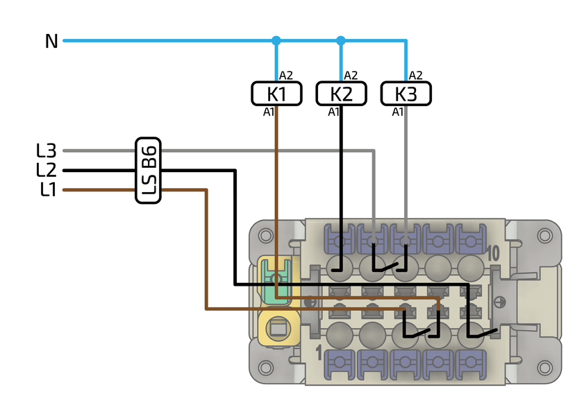
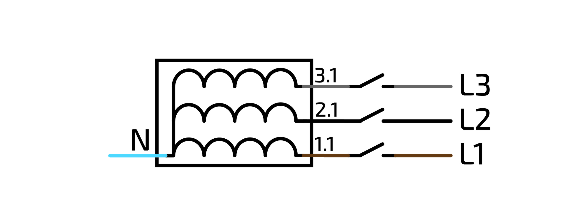
12.5. Additional AC meter
If additional meters have been installed for monitoring other consumers or generators, these must be integrated into the circuit in accordance with the manufacturer’s instructions.
The communicative integration is shown below using a 3-phase sensor without current transformer as an example.
Only meters approved by Heckert Solar can be integrated.
The meter of the first generator is always integrated with Modbus ID 6. All others in ascending order. The baud rate must be 9600.
|
|
|
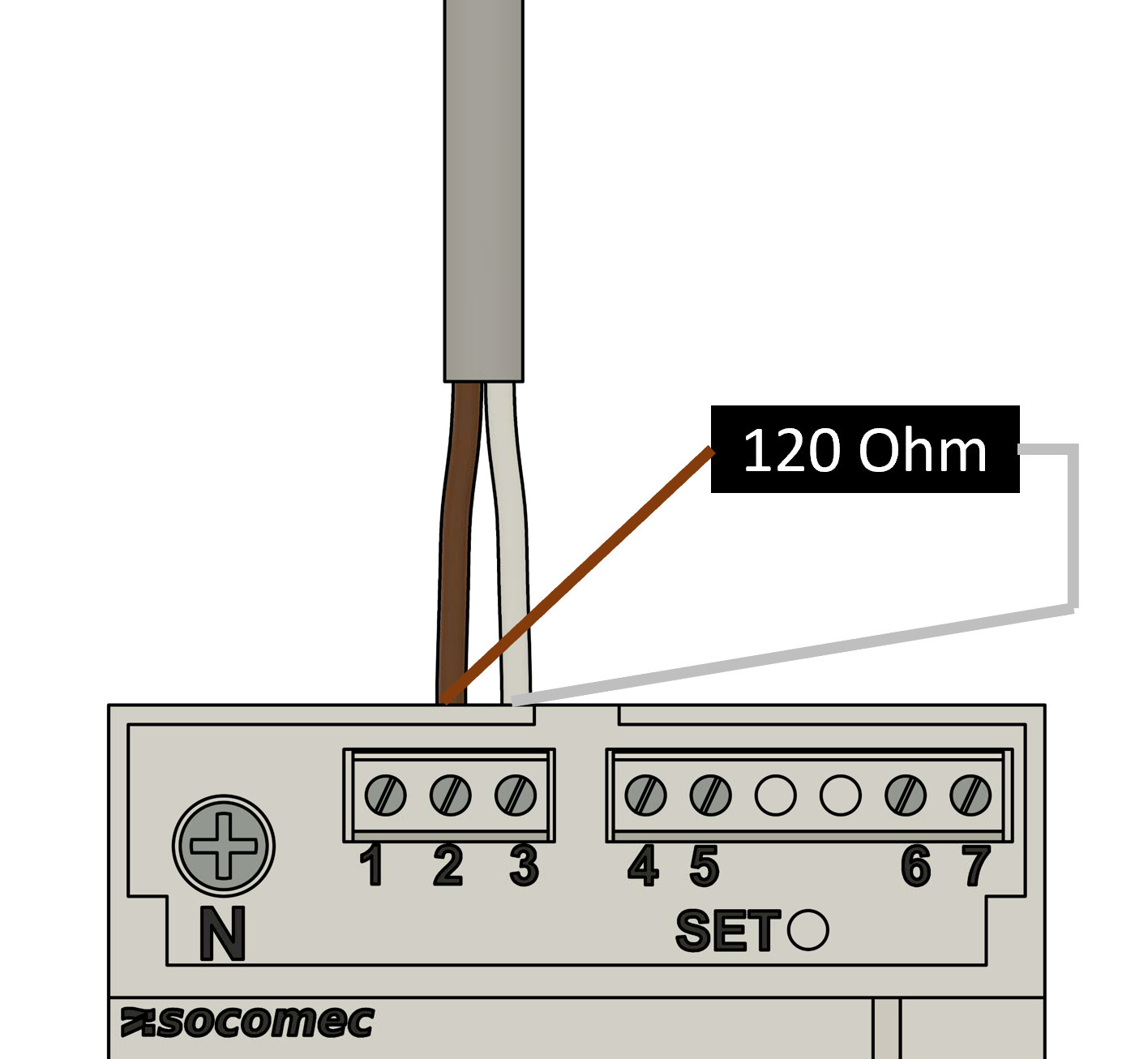
Am Beispiel SOCOMEC E24
|
|
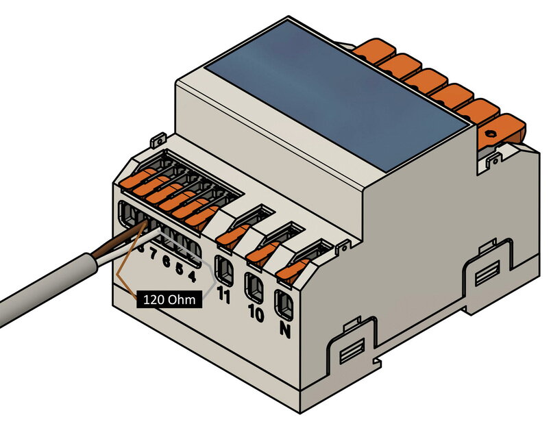
Am Beispiel KDK 4PU
|
|
If several meters are to be installed, they can be connected in series for communication purposes. For this purpose, the first meter can be bridged to the second, etc. The Modbus address must be set in ascending order. |
|
Nach der Installation der Komponenten muss die App noch installiert werden. |
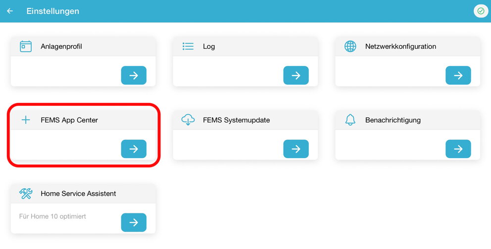
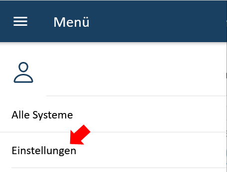
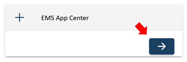
12.6. Activation of the app in the EMS App Center
After installing the hardware EMS extension, it still needs to be activated in the App Center. To do this, proceed as follows:
|
|
|
|
|
|
|
|
|
|
|
|
|
|
|
|
|
|
|
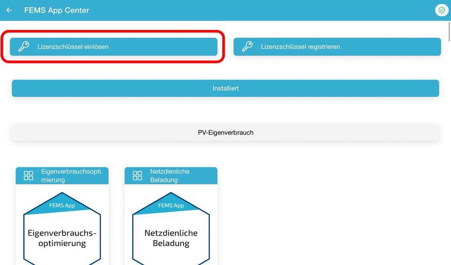
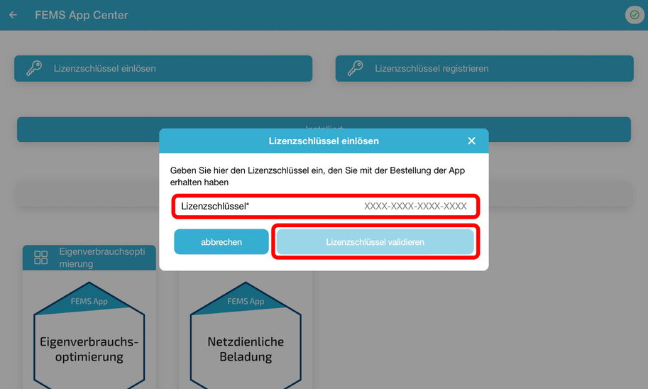
12.7. Installation weiterer EMS-Apps
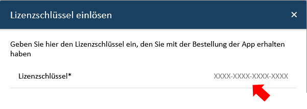
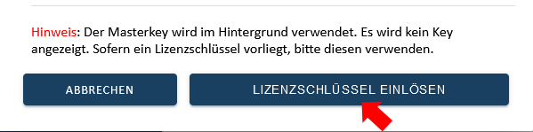
Mit der Bestellung der EMS-App haben Sie einen 16-stelligen Lizenzschlüssel erhalten. Mittels diesem Lizenzschlüssel können Sie die App eigenständig im EMS-App Center einlösen.
|
|
|

|
|
|
|
|
|

|
|
|
|
|
|
|
|
|
|

|
|
13. Controlling the inverter externally
There are various ways to override the inverter from external devices.
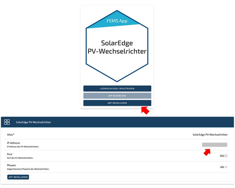
13.1. Ripple control receiver
The inverter can be controlled directly via a ripple control receiver. The following plugs supplied with the inverter are required for this.
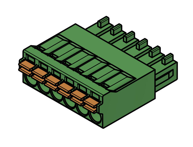
|
|
|
|
The active power of the inverter can be controlled directly by the grid operator via a ripple control receiver.
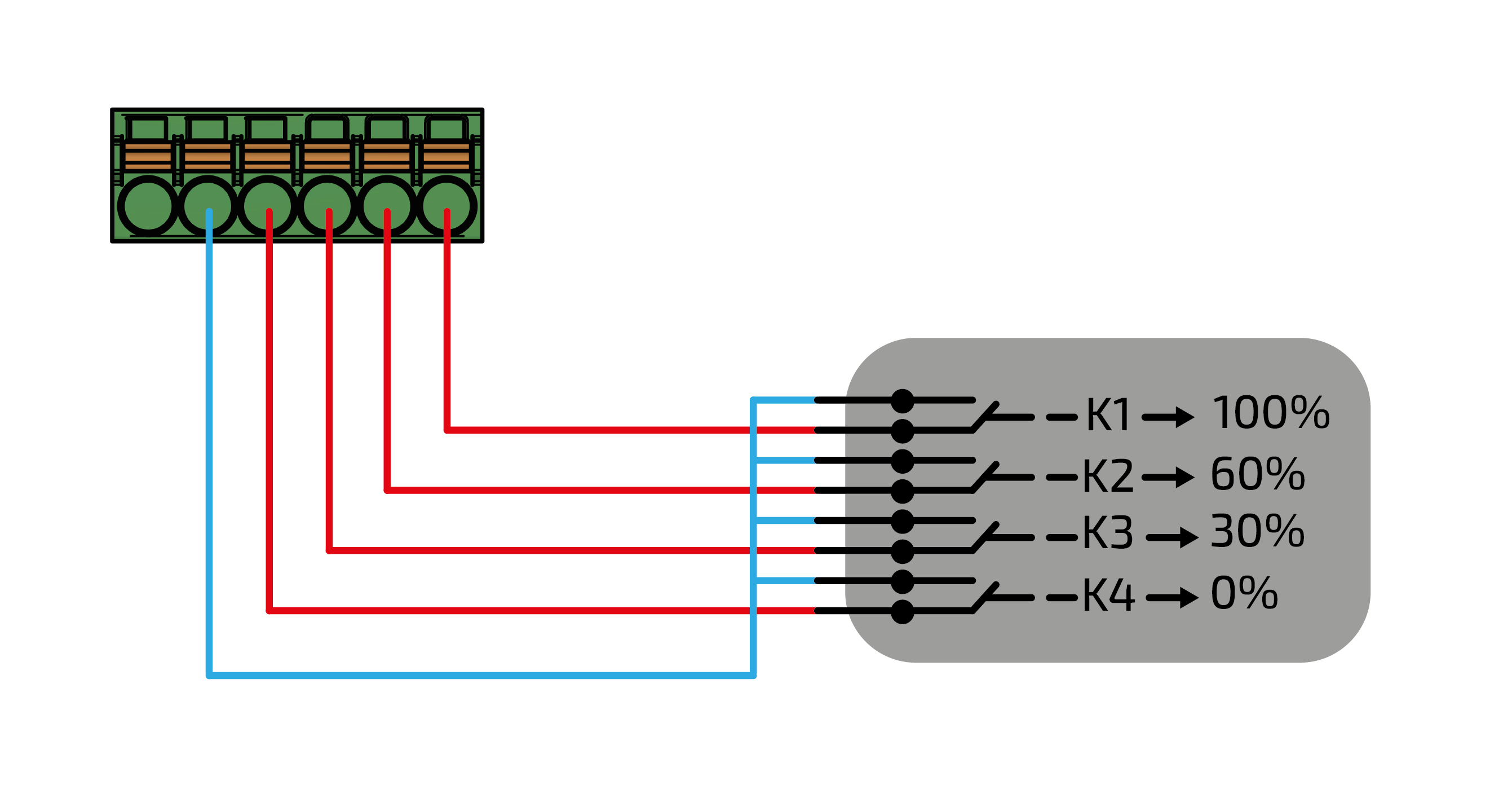
The behavior of the inverter in the various control stages is described as follows:
-
100 % → Standardsignal, Wechselrichter arbeitet ohne Einschränkungen.
-
60 % → Wechselrichter Ausgangsleistung wird auf 60 % reduziert.
-
30 % → Wechselrichter Ausgangsleistung wird auf 30 % reduziert.
-
0 % → Inverter output power is reduced to 0 %.
If other inverters are used, these must also be connected separately to the ripple control receiver; how exactly depends on the grid operator and the RCR used.
|
In the event of a curtailment to 0 %, the grid feed-in of the inverter is completely stopped, i. e. the consumption is completely supplied from the grid. |
|
|
|
|
|
|
|
Variante A
|
|
Variante B
|
|
Variante A
|
|
Variante B
|

|
|
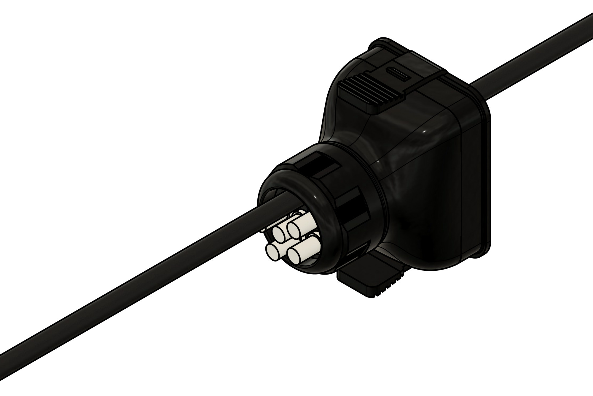
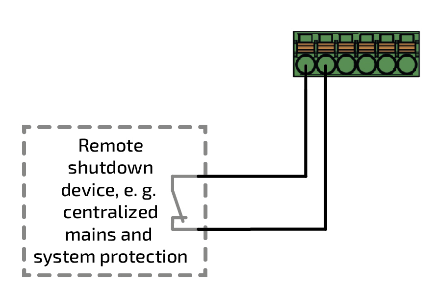
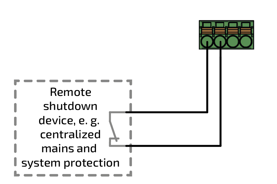
13.2. Fernabschaltung
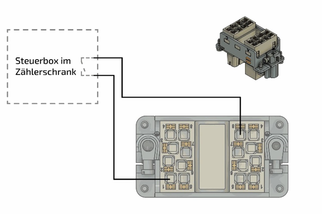
Der Wechselrichter kann bei aktivierter Fernabschaltung, z. B. über einen zentralen NA-Schutz, vom Netz getrennt werden. Hierfür wird einer der nachfolgenden Stecker, die dem Wechselrichter beiligen, benötigt.
|
|
Variante A
|
|
Variante B
|
|
|
|
Der Notstromabgang ist (wenn aktiviert) weiterhin aktiv und versorgt die Notstrom-Verbraucher. |
|
|
|
|
Variante A
|
|
Variante B
|
|
|
Variante A
|
|
|
Variante B
|
|
|
|
Mit dieser Methode kann auch die P,ave-Überwachung angeschlossen werden. |
13.3. § 14a Energiewirtschaftsgesetz (EnWG)
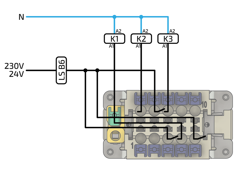
The Inverter can be limited to a maximum reference power of 4.2 kW. The digital input of the EMS must be assigned for this.
|
|
14. Troubleshooting
14.1. Fehler im Online-Monitoring
The system status can be checked after logging in at the top right using the color of the symbol. A green tick indicates that everything is OK, an orange exclamation mark indicates a warning (Warning) and a red exclamation mark indicates an error (Fault).
14.1.1. Fault display

|
System status: Everything is OK |

|
System state: Warning |

|
System state: Error (Fault) |
14.1.2. Troubleshooting
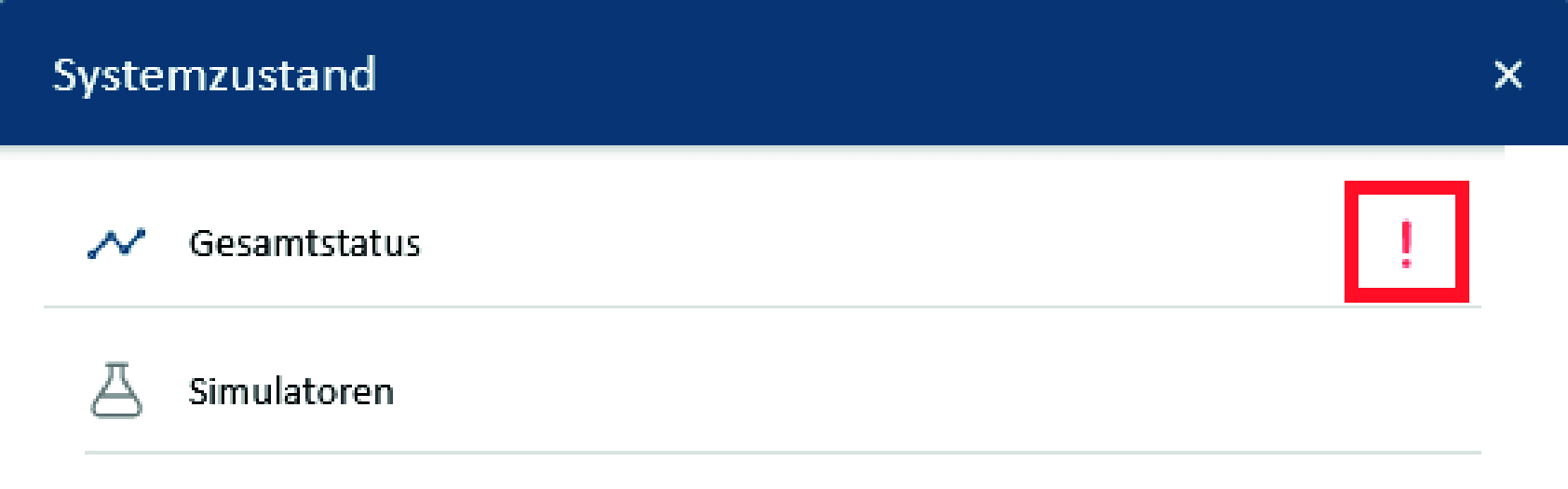
|
You can get a detailed overview of an existing warning or error by clicking on the exclamation mark in the top right-hand corner. |

|
The scroll bar can be used to examine the origin of the warning or error in more detail. |

|
Clicking on the icon (down arrow) displays a more detailed error description depending on the error. |
In the example above, an incorrect reference for the network counter was intentionally entered for test purposes, which is why the controller fails to run.

|
Under certain circumstances it can happen that the EMS is not accessible and the adjacent error message appears. |
Wenn das EMS offline ist, folgen Sie den Schritten, die unter der Meldung angezeigt werden.
14.2. Symphon-E 6, 10 & 15 inverter
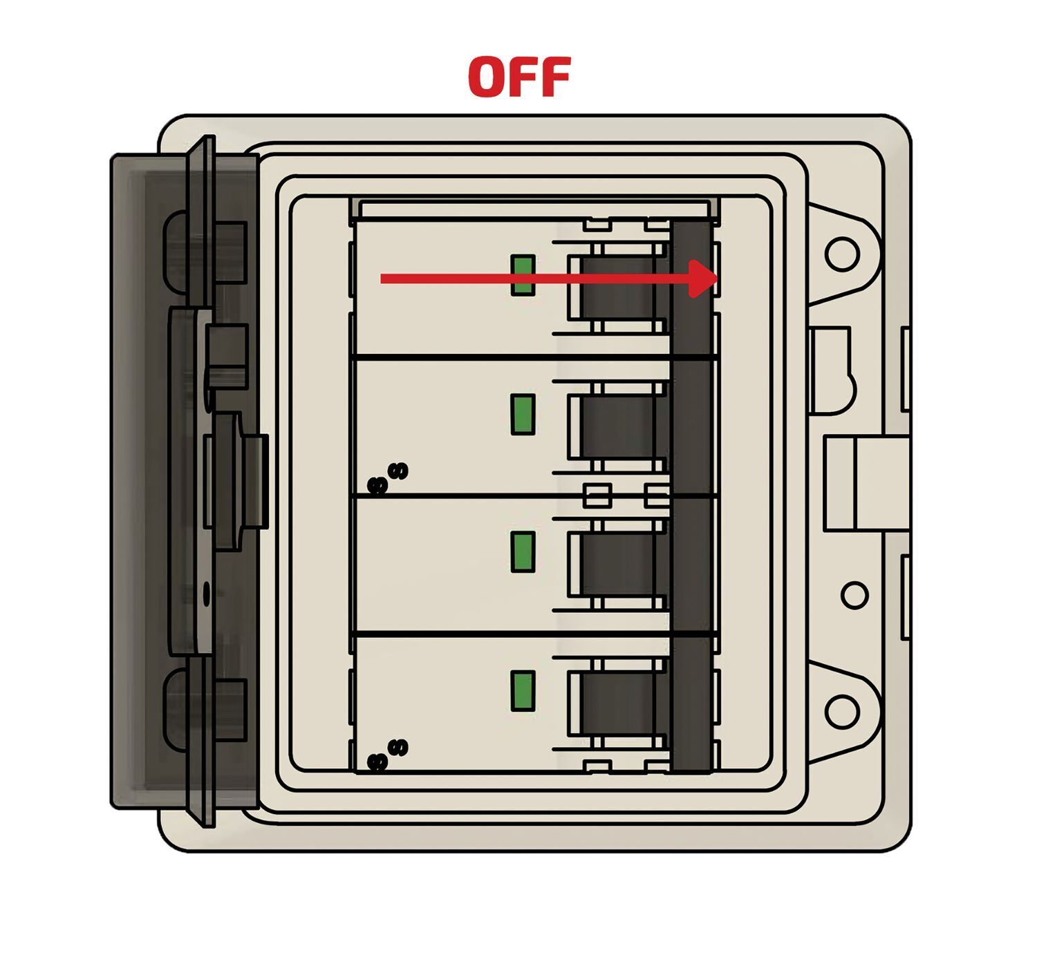
14.2.1. Fault display
Faults are indicated by a red LED next to "SYSTEM".
Drehfeld des Netzanschlusses
-
Überprüfen Sie, ob am Netzanschluss ein Rechtsdrehfeld anliegt.
-
Ansonsten kontaktieren Sie den Heckert Solar-Service. Die Kontaktdaten finden Sie im Abschnitt Service. Durch die LEDs werden weitere Informationen zum Zustand des Wechselrichter angezeigt.
| Display | Status | Description |
|---|---|---|

|

|
The inverter is switched on and in standby mode. |

|
The inverter is starting and is in self-test mode. |
|

|
The inverter is running normally in grid-parallel or stand-alone mode. |
|

|
Overloading of the RESERVE output. |
|

|
An error has occurred. |
|

|
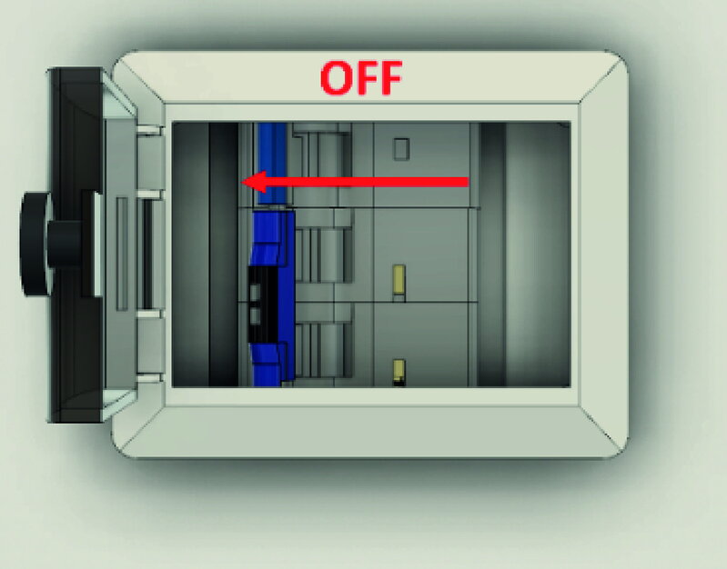
The inverter is switched off. |
|

|
|
The grid is anomalous and the inverter is in stand-alone mode. |
|
|
The grid is normal and the inverter is in parallel mains operation. |
|
|
|
RESERVE is switched off. |
|

|
|
The inverter is not connected to the Internet. Communication takes place via the EMS box. Therefore, there is no LED indication here. |
14.3. Battery tower
14.3.1. Fault display
Errors are displayed on the Symphon-E BMS box via a red LED.
The various errors are indicated by LED codes.
Speicher-Status |
Speicher-Information |
LEDs |
|||||
blau/rot |
1 |
2 |
3 |
4 |
|||
Boot-Lader |
|||||||
Starten |
Master/Slave |
||||||
Parallel-Box |
|||||||
Extension Box |
|||||||
Prüfmodus |
Einzel- oder Parallelverschaltung |
||||||
SoC-Display |
|||||||
Laden |
0 % bis 25,0 % SoC |
||||||
25,1 % bis 50,0 % SoC |
|||||||
50,1 % bis 75,0 % SoC |
|||||||
75,1 % bis 99,9 % SoC |
|||||||
100 % SoC |
|||||||
Entladen und Standby |
100%-75,1% |
||||||
75,0%-50,1% |
|||||||
50,0%-25,1% |
|||||||
25,0%-0% |
|||||||
Fehler |
Überspannung |
||||||
Unterspannung |
|||||||
Übertemperatur |
|||||||
Untertemperatur |
|||||||
Überstrom |
|||||||
SoH zu tief |
|||||||
Int. Kommunikation |
|||||||
Ext. Kommunikation |
|||||||
Adressfehler Parallel |
|||||||
Adressfehler Module |
|||||||
BMS-Box-Sicherung |
|||||||
Modulsicherung |
|||||||
Kontaktfehler |
|||||||
Isolationsfehler |
|||||||
BMS-Fehler |
|||||||
Blue permanently on |
|
blinking blue |
|
Blue flashing quickly |
|
Red permanently on |
14.3.2. Troubleshooting
Wenn Störungen nicht behoben werden können oder bei Störungen, die nicht in der Störungsliste erfasst sind, muss der Heckert Solar-Service kontaktiert werden. Siehe Abschnitt Service.
14.4. Fault list
| Component | Disturbance | Measure |
|---|---|---|
Battery module |
The battery module has become wet |
Do not touch |
Battery module |
The battery module is damaged |
A damaged battery module is dangerous and must be handled with the utmost care. |
14.5. Service
If the system malfunctions, contact Heckert Solar Service:
Phone: +49 (0) 371 458 568 100
E-mail: symphon-e@heckert-solar.com
Unsere Servicezeiten:
Mo.-Do. 08:00 bis 12:00 Uhr | 13:00 bis 17:00 Uhr
Fr. 08:00 bis 12:00 Uhr | 13:00 bis 15:00 Uhr
15. Technical maintenance
15.1. Tests and inspections
|
When carrying out inspection work, ensure that the product is in a safe condition. Improperly performed inspections can have serious consequences for people, the environment and the product itself. |
|
Inspektionsarbeiten sind ausschließlich von ausgebildeten und befähigten Fachkräften durchzuführen. |
|
The maintenance instructions of the component manufacturer must be observed for all individual components. |
Kontrollieren Sie das Produkt und die Leitungen regelmäßig auf äußerlich sichtbare Beschädigungen. Bei defekten Komponenten kontaktieren Sie den Heckert Solar-Service. Reparaturen dürfen nur von der Elektrofachkraft vorgenommen werden.
15.2. Cleaning
Reinigungsmittel: Durch die Verwendung von Reinigungsmitteln kann der Stromspeicher und seine Teile beschädigt werden.
Es wird empfohlen. den Stromspeicher und alle seine Teile ausschließlich mit einem mit klarem Wasser befeuchteten Tuch zu reinigen.
|
The entire product must be cleaned regularly. Only suitable cleaning agents may be used for this purpose. |
15.3. Wartungsarbeiten
No regular maintenance work needs to be carried out on the system, but check the status of your Storage unit regularly.
|
Eine regelmäßige Neu-Referenzierung des Speichers wird empfohlen, d. h., dass dieser vollständig entladen (SoC = 0 %) und anschließend wieder vollständig beladen werden muss (SoC = 100 %), da es sonst ggf. zu Kapazitätsverlusten kommen kann. |
16. Information for fire departments when handling Heckert Solar home and commercial battery energy storage systems
The Heckert Solar home and commercial systems operate in the low-voltage range, which means that they are operated with voltages of less than 1,500 volts direct current (DC) and less than 1,000 volts alternating current (AC).
It may be useful to install an additional switch that disconnects the building from the emergency power supply. This makes it easier for the fire department to act safely and quickly in an emergency.

For a precise procedure for emergency services, it is recommended to ask the relevant fire department schools and request the corresponding information sheets and pocket cards for battery storage systems.
18. Transportation
This section contains information on external and internal transportation of the product.
Transportation is the movement of the product by manual or technical means.
-
Only use suitable and tested lifting gear and hoists for transportation!
|
Risk due to lifted Loads! |
|
Check that the parts and outer packaging are in perfect condition. |
|
Überzeugen Sie sich, dass
|
Notes:
|
|
Legal regulations |
19. Dismantling and disposal
19.1. Prerequisites
-
The power supply to the Battery energy storage unit is interrupted and secured against being switched on again.
|
Sharp and pointed edges
|
19.2. Dismantling
-
The electrical Energy storage system must only be dismantled by authorized electricians.
-
Dismantling work may only be carried out when the system has been taken out of operation.
-
Before starting disassembly, all components to be removed must be secured against falling, tipping over or moving.
-
Dismantling work may only be carried out when the system is shut down and only by service personnel.
-
The dismantling instructions of the component manufacturers (see appendix, Other applicable documents) must be observed.
-
The current laws, regulations and standards must be observed when transporting the battery modules (e.g. Dangerous Goods Transportation Act - GGBefG).
19.3. Waste disposal
-
The Heckert Solar storage system must not be disposed of with normal household waste.
-
The Symphon-E 20 & 30 is RoHS- and REACH-compliant.
-
Disposal of the product must comply with local regulations for disposal.
-
Avoid exposing the battery modules to high temperatures or direct sunlight.
-
Avoid exposing the battery modules to high humidity or corrosive atmospheres.
-
Dispose of the electrical energy storage system and the batteries it contains in an environmentally friendly manner.
-
Contact Heckert Solar GmbH to dispose of the used batteries.
|