Symphon-E App Power-to-Heat
1. Introduction
Dear customer,
Thank you for choosing the "Symphon-E App Power-to-Heat". You are welcome to send us your suggestions so that we can further improve the quality of our products.
2. Installing the app
When you ordered the "Symphon-E App Power-to-Heat", you received a 16-digit license key. You can use this license key to redeem the app independently in the EMS App Center.
Instructions on how to proceed can be found here.
|
For the integration of several Power-to-Heat applications, the purchase of a single Symphon-E App is required. |
3. SG-Ready heat pump
3.1. Prerequisites
To integrate an SG-Ready heat pump with the "Symphon-E App Power-to-Heat" is required:
-
Home-EMS box with two free relay contacts or
-
Extension of the home EMS box by a TCP 8-Channel Relay Board for further relay contacts and
-
a heat pump with the "Smart Grid Ready" label
| Depending on the type of heat pump (heat pump for heating purposes vs. heat pump for domestic water), a free relay contact may also be sufficient (see FAQ). |
3.2. Integration
The integration of an "SG-Ready" (Smart Grid Ready) heat pump into the energy management system is an advanced form of sector coupling of electricity and heat.
The controller ensures that the heat pump slightly overheats the thermal energy storage at times when excess PV power is available in order to save electrical energy at times when there is no cheap excess power available.
3.2.1. Operating states
Four different switching states have been realized for the SG-Ready control, which correspond to the following list:
-
Lockout: Operating state 1 (1 switching state, with terminal solution: 1:0): This operating state is downward compatible with the grid operator lockout, which is often switched at fixed times, and comprises a maximum of 2 hours of "hard" lockout time.
-
Normal operation: Operating state 2 (1 switching state, for terminal solutions: 0:0): In this circuit, the heat pump runs in energy-efficient normal operation with proportionate heat storage filling for the maximum two-hour grid operator block.
-
Switch-on recommendation: Operating state 3 (1 switching state, with terminal solution 0:1): In this operating state, the heat pump runs within the controller in boosted operation for space heating and domestic hot water preparation. This is not a definitive start-up command, but a switch-on recommendation corresponding to the current boost.
-
Switch-on command: Operating state 4 (1 switching state, with terminal solution 1:1): This is a definitive start-up command, insofar as this is set in the control settings.
As there is no official standard for heat pump inputs, some manufacturers activate the operating states via a voltage (applied to the inputs). Other manufacturers use a connection between two inputs of the heat pump instead. Due to this fact, the app was designed to be universal. This must now be adapted to the control of the heat pump. This can mean that a control voltage is applied to the relays, which is then forwarded to the respective heat pump input (when the relay is active) (depending on the heat pump).
The table below summarizes the four different operating states, the corresponding designations in the widget and the circuits of the individual relays.
| Name in widget | Relay 2 | Relay 3 | |
|---|---|---|---|
Operating status 1 |
Lock |
Closed |
Open |
Operating state 2 |
Normal operation |
Open |
Open |
Operating state 3 |
Switch-on recommendation |
Open |
Closed |
Operating state 4 |
Switch-on command |
Closed |
Closed |
As soon as the "Symphon-E App Power-to-Heat" for integrating an SG-Ready heat pump has been installed on your system, you will see this widget in your monitoring:
Click on the widget to open the detailed view:
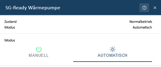
It displays the current status and mode.
Here you have the option of switching between the two operating modes Manual and Automatic:
-
Manual
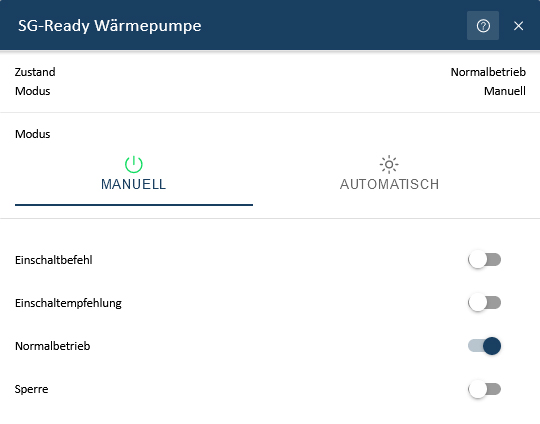 Figure 3. Operating mode "On"
In Manual mode, the operating states of the heat pump can be set manually.
-
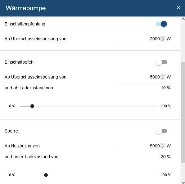
Automatic
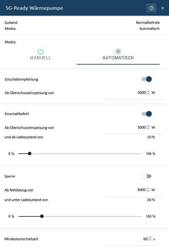
In "Automatic" mode, the operating states of the heat pump can be set using the parameters surplus feed-in, mains supply and state of charge of the electrical energy storage. The built-in hysteresis ensures that the relays do not constantly switch on and off. This can be implemented via the minimum switchover time (in seconds).
|
The corresponding widget in the historical view displays the behavior of the heat pump over time.
In addition, you can track the duration of the individual operating states of the heat pump used in the historical view in Online Monitoring (see Widget - Historical view (1)):
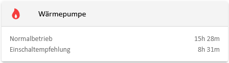
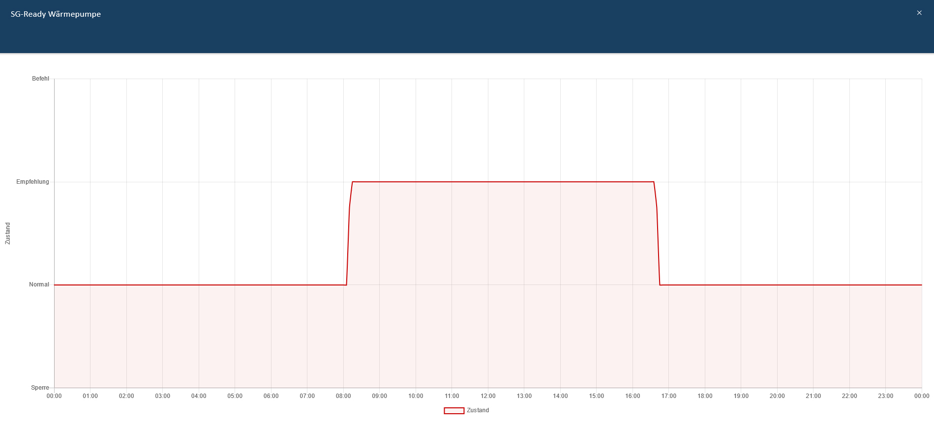
In the example above, only the operating state switch-on recommendation was selected in automatic mode. This is activated at times when excess PV power is available. At other times, the heat pump operated in normal mode.
| You can find more information about the SG-Ready label for heat pumps at https://www.waermepumpe.de/normen-technik/sg-ready/ |
3.3. FAQ - Frequently Asked Questions
Below you will find the answers to Frequently Asked Questions about our app
1. I use a heat pump for domestic water with SG Ready label, which only has one controller/potential-free contact. Can I still use the app?
Yes, with these heat pumps the controller is used for automatic control and enables the hot water setpoint temperature to be increased for the purpose of thermal storage. The app can also be used here. However, when using it, it must be noted that only two states (0 or 1) can be switched with only one potential-free contact. We therefore recommend selecting the following two combinations of operating states.
-
Switch-on recommendation (0 | 1) or normal operation (0 | 0) or
-
Switch-on command (1 | 1) or normal operation (0 | 0)
Technically, the combinations above do not differ for the heat pump, as in both cases a contact is switched and the flow temperature is raised. The difference lies purely in the selection of parameterization options in the app. With the first combination, the relay is only switched depending on the surplus feed-in. With the lower combination, the state of charge of the electrical energy storage can be added as an additional threshold value.
The example below shows the use of the app with a Stiebel Eltron WWK200 heat pump for domestic water. The heat pump is only connected to the EMS connection box (Harting plug) via a potential-free contact.
The upper of the two combinations was chosen here. From an excess feed-in of 2000 W, the potential-free contact of the heat pump is switched. The compressor then increases the flow temperature from 55 °C to 65 °C. Regardless of whether the signal is still present, the heat pump now remains in this increased operating mode for at least 20 minutes. If the signal is still present after 20 minutes, the heat pump remains in this mode. Otherwise, it switches back to normal operating mode (normal operation).
4. Heating element
4.1. Why should a heating element be integrated into the energy management system?
The integration of an electric heating element into the energy management system is the simplest form of sector coupling of electricity and heat. If the electrical energy storage system is fully charged during the day, the PV surplus must be fed into the public grid with little or no remuneration. Instead, it makes more sense to increase self-consumption and use the PV surplus electricity for heating/cooling the residential building or for hot water preparation (e.g. for a hot water buffer storage or pool heating).
The app enables the integration of a heating element dynamically in three power levels.
The table below shows this as an example for a 6 kW heating element. For a heating element with a different power value, the power levels are adjusted accordingly.
4.2. Advantages of a heating element in the energy management system
-
Flexibility
Quick and easy activation, depending on the heat requirement.
-
Integration of renewable energies:
Combined with renewable energy sources such as solar or wind energy, heating elements make surplus energy usable. If more energy is generated than is needed on a sunny day, this surplus energy can be used to heat water or heat rooms.
-
Load management
When activated at times of lower demand or cheaper tariffs, heating elements can help to control the consumer load on the electricity grid. This can reduce operating costs and increase the efficiency of the energy management system.
-
Energy efficiency
Heating elements enable a higher overall energy efficiency of the system. They are able to provide heat quickly, even without large storages.
-
Cost efficiency
Heating elements are relatively inexpensive to purchase and install, which makes them an attractive option for supplying heat in an energy management system.
Overall, heating elements help increase energy efficiency, reduce costs and promote the integration of renewable energies.
4.3. Prerequisites
The following is required to integrate a heating element into "Symphon-E App Power-to-Heat":
-
EMS with three free relay contacts or
-
EMS-Relayboard-8-channel TCP with three free relay contacts.
-
Three-phase electric heating element with neutral, stage-controlled circuit.
| If a heating element is to be operated with more than 2 kW power per phase, the use of load-shedding relays is also required! |
Level |
Function |
|---|---|
Level 0 |
Heating element switched off |
Level 1 |
Power 2000 W |
Level 2 |
Power 4000 W |
Level 3 |
Power 6000 W |
4.4. Heating element with meter
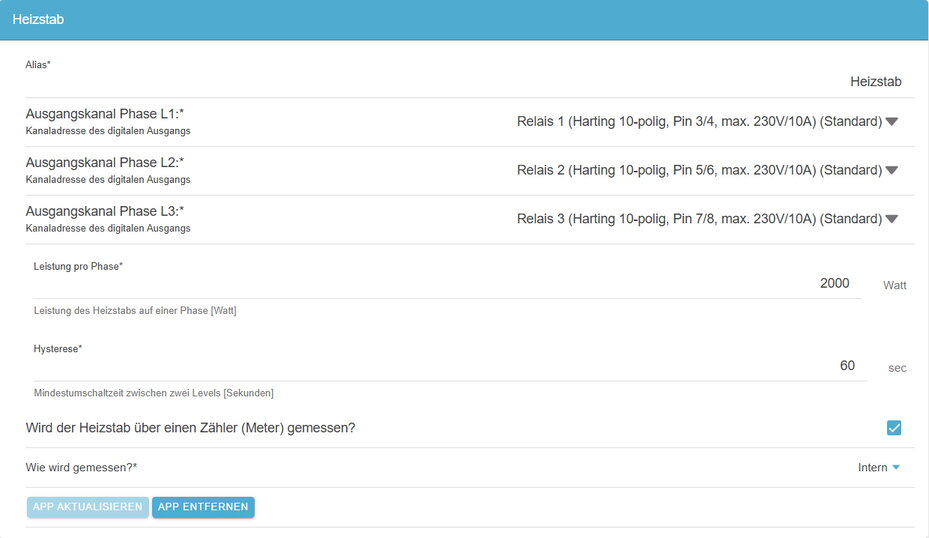
When installing the heating element app, you can select whether the internal meter should be used:
4.5. Function and operating modes
As soon as the "Symphon-E App Power-to-Heat" for integrating a heating element has been installed on your system, you will see this widget in your monitoring:
Click on the widget to open the detailed view:
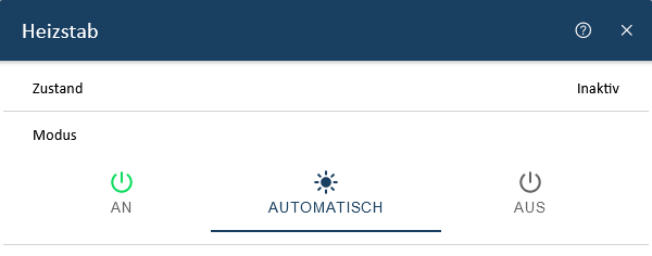
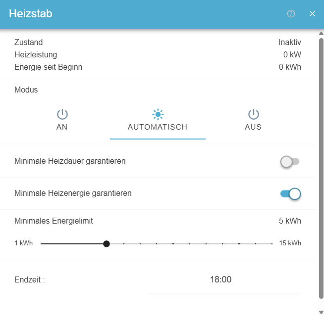
Here you have the option of switching between three operating modes: On, Automatic and Off.
-
On
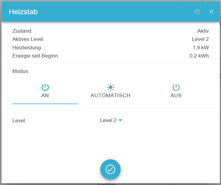
In On mode, you switch the heating element on manually.
You can also select the "Level" (see table above) at which the heating element is to be operated.
-
Automatic
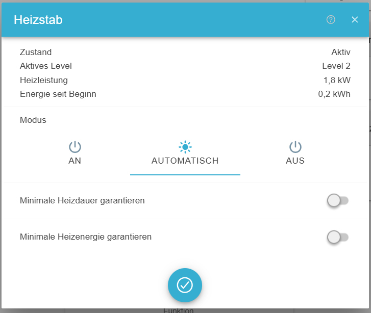
In Automatic mode, the heating element is activated as soon as excess current is fed into the grid.
You have the following options here:
-
Guarantee minimum heating time: Here, the set number of hours is switched on until the set end time of the heating element. If the heating element is switched on during the day because a surplus had to be used during PV generation, these hours are also taken into account.
-
The heating element must be active at the selected level and runtime until the end time, regardless of whether excess PV current is available or not.
-
Example: A minimum runtime of one hour until 5 pm was selected. Due to cloud cover, no PV surplus is available. However, as the heating element should be active for at least one hour due to the configuration, the heating element is switched on at 4 pm to guarantee a minimum runtime of one hour until 5 pm.
-
| The minimum runtime has no limiting effect on the operation of the heating element, provided there is sufficient surplus PV available. The temperature control on the heating element is ultimately the limiting factor here. |
-
Guarantee minimum heating energy: Here, the set heating energy in kWh is converted by the heating element up to the set end time of the heating element. The energy converted in the heating element today due to excess PV is also taken into account here.
-
This setting ensures that a certain minimum amount of energy (in kilowatt hours, kWh) is introduced via the heating element — regardless of how long this takes.
-
This setting is used, for example, if you want to ensure that a certain amount of energy (e.g. from a PV system) is consumed in full, even if the output of the heating element fluctuates or the heating duration is extended as a result.
-
Example: The heating element should feed at least 3 kWh of energy into the system. If it is only operated with 1 kW power, this takes 3 hours. If it is heated with 3 kW, it takes 1 hour - but in both cases 3 kWh are supplied.
-
|
New function: Heating element with meter Minimum energy limit: Setting which energy you would like to have in which period. The PV surplus is taken into account first. If this is not sufficient, heating is provided via grid withdrawal towards the end of the set end time. |
-
Off
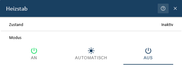
In Off mode, the heating element is switched off permanently.
You can also track the switch-on times of the heating element in the historical view in Online Monitoring (see Heating element — History (1)):
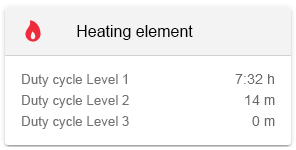
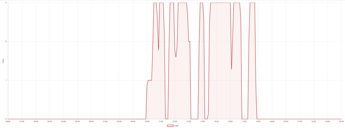
The power consumption of the heating element can theoretically be calculated as follows using the switch-on times:
Power consumption = Duty cycle level 1 (in hours) * 2 kW + duty cycle level 2 (in hours) * 4 kW + duty cycle level 3 (in hours) * 6 kW
Calculation for the example above:
Duty cycle level 1: 7.53 hrs * 2 kW = 15.06 kWh
Duty cycle level 2: 0.23 hrs * 4 kW = 0.92 kWh
Duty cycle level 3: 0 kWh
Power consumption heating element: 15.06 kWh + 0.92 kWh = 15.98 kWh
|
In the calculation above, the app is used in combination with a 6 kW heating element. For a heating element with a different power value, the power levels are adjusted accordingly. |
| If the heating element has a maximum temperature or similar stored, it is possible that no power is drawn, even if the relay contact is switched on. In this case, the direct conversion to kWh would not be correct. Online Monitoring therefore does not use this automatic conversion. |
| By the way: The 8-channel TCP relay board can switch up to 10 A directly, i. e. no separate contactors are required to control the heating element for a three-phase heating element with 6 kW power (= 3 x 2 kW). You could also operate a more powerful heating element with the "Symphon-E App Power-to-Heat". In this case, the different power must be configured in the software. Please contact our service department for this. |
5. Combined heat and power plant (CHP)
5.1. Why a CHP unit?
A CHP unit uses combined heat and power (CHP) to generate electricity and heat at the same time, which can be supplied to heating systems. The relationship with external electricity can be reduced, which saves costs. A CHP therefore makes you less dependent on electricity price providers and electricity price trends. Furthermore, a CHP requires neither sun nor wind to produce electricity and heat. CHPs are available in various designs and sizes and offer a high efficiency of up to 90 % when producing heat and, depending on the operating mode, from 10 to 40 % when generating electricity.
5.2. Advantages of a CHP unit
-
Energy efficiency:
CHP systems generate electricity and heat at the same time (combined heat and power), which increases overall energy efficiency. An EMS can optimize the operation of the CHP system to minimize energy consumption.
-
Cost savings:
Using waste heat for heating or process heat can reduce energy costs. An EMS helps determine the optimum time to operate the CHP in order to benefit from lower electricity prices.
-
Load management:
An EMS can identify and control peak loads so that the CHP can be used in a targeted manner to reduce the load on the grid and save costs for grid usage fees.
-
Integrating renewable energies:
In combination with renewable energy sources (e. g. solar or wind energy), an EMS can better balance generation and consumption, reducing the use of fossil fuels.
-
Flexibility and security of supply:
A CHP can be ramped up and down quickly, which makes it flexible. An EMS can use this flexibility to respond to fluctuations in energy demand or generation.
-
Reduction of CO2 emissions:
Thanks to their higher efficiency and the option of integrating renewable energies, CHPs help reduce greenhouse gas emissions.
5.3. Prerequisites
The following is required to integrate a CHP with the "Symphon-E App Power-to-Heat":
-
Home-EMS box with one free relay contact or
-
Extension of the home EMS box by a TCP 8-Channel Relay Board for further relay contacts and
-
a CHP that can be switched on and off via relays.
5.4. Integration
The integration of a CHP into energy management systems is an advanced form of sector coupling (electricity and heat).
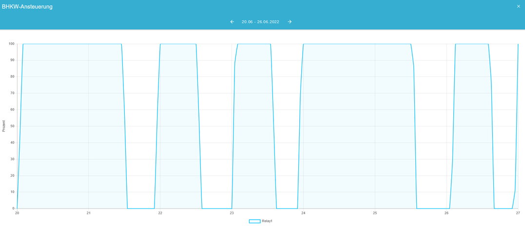
As soon as the "Symphon-E App Power-to-Heat" for integrating a CHP has been installed on your system, you will see this widget in your monitoring:
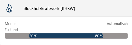
In this view you can see the current operating mode and whether the CHP is currently active or inactive.
Click on the widget to open the detailed view of the app:
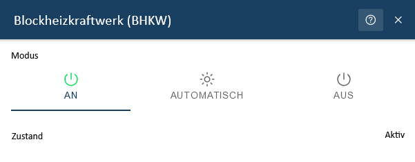
Here you have the option of switching between three operating modes:
-
On: Forced switch-on
-
Automatic
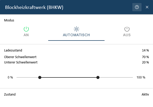
The "Automatic" operating mode takes advantage of the CHP’s ability to generate electricity regardless of the time of day and weather conditions.
-
State of charge: Current state of charge of the electrical energy storage.
-
Upper threshold value: State of charge of the electrical energy storage above which the CHP is switched off.
-
Lower threshold value: State of charge of the electrical energy storage below which the CHP is switched on.
If the state of charge falls below the lower threshold value, a switch-on signal is sent to the CHP. This prevents more expensive electricity from being drawn from the grid. If the state of charge exceeds the upper threshold value, the switch-on signal is withdrawn to prevent unnecessary grid feed-in of CHP electricity.
The following table shows the preset switching thresholds (see Detail widget):
| Change in state of charge | Change in switching state |
|---|---|
20 % → 19 % |
Off → On |
70 % → 71 % |
On → Off |
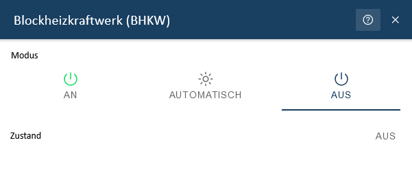
-
Off: Forced switch-off
The behavior of the CHP over time can be viewed via the associated widget in the historical view.